Introduction to MAP sensor:
The intake manifold of an engine can be equipped with a “Manifold Air Pressure sensor”, abbreviated as MAP sensor. This pressure sensor measures the absolute pressure in the intake manifold. The sensor can be mounted on the intake manifold, or externally connected with a small tube. The vacuum or pressure is converted by the sensor into a signal voltage created from the supply voltage, making the MAP sensor an active sensor. The measuring range often runs from 20 – 300 kPa (0.5 to 3 bar). We distinguish between the MAP sensor for an atmospheric engine and a boost pressure sensor for an engine with pressure management.
MAP sensors are used to measure engine load. The manifold (vacuum) pressure is an indicator of the filling rate. Fuel injection is partly determined by the value the MAP sensor registers.
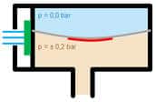
In the MAP sensor, two air chambers are separated by a membrane. The pressure in the MAP sensor causes the membrane in the sensor to bend. In the illustration, the upper section experiences the outside air pressure, and the lower section experiences the vacuum. Several strain gauges are applied to this membrane to register the deflection of the membrane. A larger pressure difference causes the membrane to bend further.
The MAP sensor consists of mostly four piezo-resistive strain gauges mounted in a Wheatstone bridge configuration on a diaphragm. When the material is compressed or stretched, the resistance value of the strain gauges changes. In the Wheatstone bridge, the change in resistance is converted into a voltage change. This forms the signal voltage, which is sent to the ECU. The ECU contains an A/D converter that digitizes the voltage signal before it enters the microprocessor.
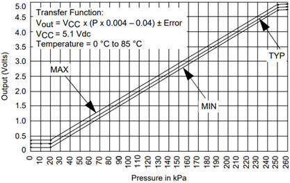
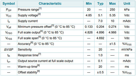
Properties of the MPX4250AP:
The output voltage level depends on the pressure in the intake manifold and ranges between 0.1 and 4.9 volts. The following image shows the characteristic of a commonly used MAP sensor of the type: MPX4250AP. The line is linear. At an atmospheric pressure of 100 kPa (equal to 1 bar), the sensor provides a voltage of about 1.8 volts at an average operating temperature (TYP).
The characteristic shows that the sensor registers nothing at p 5, 20. This means that the engine, in the case of a fully open throttle and high load, no longer relies on the value from the MAP sensor but switches to a substitute value through software. The recorded throttle opening angle provides a solution here.
The component properties of the MPX4250AP are shown in the table.
Signal voltage of an atmospheric engine:
The signal voltage of the MPX4250AP sensor in an atmospheric engine can look like this. In this graph, the throttle is intermittently opened, released, accelerated, and decelerated.
Boost pressure sensor:
Combustion engines with forced induction are equipped with a boost pressure sensor to measure the pressure in the intake path. a0This sensor is located in the air pipe (or tube) between the intercooler and the throttle body of the engine. Forced induction can be realized in the following manner:
- Diesel engines: exhaust gas turbocharger;
- Gasoline engines: exhaust gas turbocharger or mechanical supercharger, or a combination thereof.
The boost pressure sensor (also known as turbo pressure sensor or boost sensor) is essentially a MAP sensor with a broader measuring range than that of an atmospheric engine:
- Atmospheric engine: up to 1.5 bar;
- Engine with forced induction: up to 2.5 bar;
- Engine with forced induction: up to 3.5 bar.
The engine management system converts the voltage signal from the pressure sensor into a pressure signal and uses it to control the turbo’s wastegate. When a turbo with VGT is used, the position of the vanes is adjusted.
- During acceleration, the turbo needs to supply more pressure. The wastegate remains closed until the desired intake air pressure, or boost pressure, is reached.
- Upon reaching the desired boost pressure, the ECU controls the wastegate, which will partially open. The pressure is maintained or reduced by opening the wastegate more.
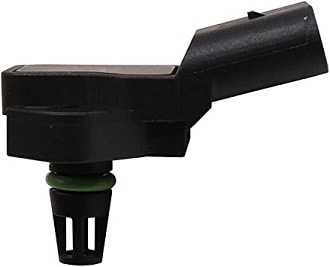
Combination with temperature sensor:
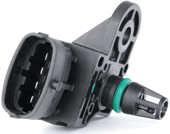
MAP sensors can be housed alongside the intake air temperature sensor in a single enclosure. This can be recognized by four connections. Temperature is an important factor for determining the injection amount.
Regarding air temperature, we can recognize the following:
- Intake air temperature should not differ by more than 5 degrees from the coolant temperature when the engine is cold;
- Intake air temperature higher than the coolant temperature: EGR valve remains open.
If there are deviations from the two points mentioned above, the ECU can generate a fault code.
Diagnosing the boost pressure sensor:
Faults with the boost pressure sensor can be identified by the following symptoms:
- Reduced engine power;
- Inconsistent pulling power during acceleration;
- Excessive fuel consumption and emissions;
- Malfunction Indicator Lamp (MIL) with related fault codes (DTCs).
Of course, with the complaints mentioned above, it is logical to read out the fault memory of the engine electronics. If the engine management system saves a fault code related to an incorrect signal from the boost pressure sensor, we can expect the following codes: P0105, P0106, P0107, P0235, P0236, P0238.
Causes of an incorrect signal may include:
- Internal wear, contamination, or even blockage of the sensor element;
- Excessive contamination in the intake channel, such as by carbon deposits in the intake manifold or the intake ports of the cylinder head;
- Exhaust blockages;
- Leakage in the air hoses;
- Wiring issue between the sensor and ECU.
Contamination in the intake path can be determined by disassembling components such as the throttle / choke body and the intake manifold, or by checking the inside of the manifold with an endoscope. Exhaust blockages can be caused by a defective catalyst core or a clogged particulate filter.
Problems with the sensor electronics or wiring between the ECU and the sensor can be investigated by studying the schematic and conducting measurements.
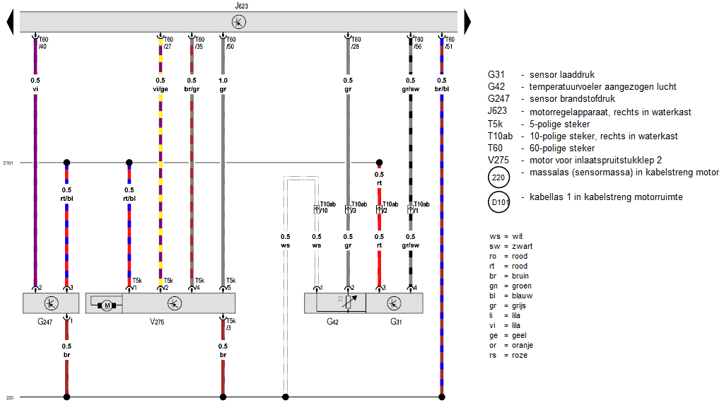
The image below shows the schematic of a boost pressure sensor. Click here for an explanation on reading schematics.
The boost pressure sensor and air temperature sensor are integrated into a single housing. The sensors share a common positive terminal (pin 3) and ground (pin 1). This indicates that it is an active sensor. The signal wire of the boost pressure sensor (pin 4 on the sensor) is gray/black in color and connects to pin 56 of the engine control unit. In this schematic, it is not deducible whether the signal is an analog voltage (AM) or digital (PWM). Measurement will clarify this.
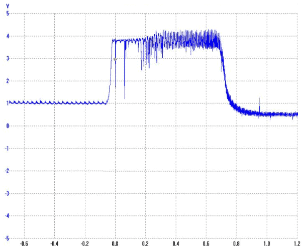
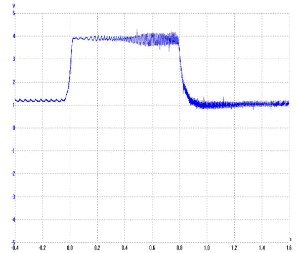
The depicted boost pressure sensor sends an AM signal (Amplitude Modulation), visible in the oscilloscope image. The voltage height translates the pressure curve relative to time. The following screenshot shows the voltage curve of a boost pressure sensor. The oscilloscope settings are: 1 volt per division and 200 ms per division.
With an idling engine, the turbo doesn’t yet produce boost pressure. The absolute pressure in the intake manifold is about 100 kPa. The sensor translates this pressure into a voltage of about 1.6 volts.
When the accelerator is pressed, the engine speed and thus turbo pressure are increased. The pressure gradually rises to 1.4 bar. At that pressure, the voltage in the oscilloscope image nearly reaches 3 volts. After that point, the accelerator pedal is released, and the boost pressure decreases.
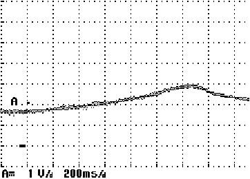
With a defect in the boost pressure sensor or wiring, one may notice irregularities in the signal. The voltage signal should range between 0.5 and 4.5 volts with a supply voltage of 5 volts. The two images below show a signal with a fault (left) and without a fault (right).
On the page troubleshooting sensor wiring, measurement techniques for various types of sensors, including this active sensor, are described, along with possible issues and causes.