EnglishEN
  • NederlandsNL
MVWautotechniek.nl
  • Internal Combustion Engines
  • Electric Drive
  • Body
  • Comfort, Safety, HVAC
  • Electronics
  • Chassis
  • Transmission
  • Diagnostic Techniques
  • Other
  • Search
  • Internal Combustion Engines
  • Electric Drive
  • Body
  • Comfort, Safety, HVAC
  • Electronics
  • Chassis
  • Transmission
  • Diagnostic Techniques
  • Other
  • Search

Manual Transmission

Topics:

  • Introduction
  • Single and Double Reduction
  • Transmission in Longitudinal or Transverse Direction
  • Gears and Speeds
  • Transmission Operation
  • Synchronization Device
  • Disassembling the Transmission
  • Constant Mesh
  • Sliding Mesh
  • Gear Ratios

Introduction:
The purpose of a transmission is to adjust the engine speed and thus the available engine torque and power to different driving conditions. This can be during acceleration or deceleration, transporting a heavy load, driving uphill or downhill, and changes in air and rolling resistance that can occur while driving. Shifting to a more favorable gear in these different conditions often leads to better fuel economy and more torque and power.
In a low gear (such as second gear), more engine torque is available than in a higher gear (such as fourth gear). This is because the crankshaft of the engine makes more revolutions in second gear and accelerates much faster than in a higher gear. Therefore, it is wiser not to drive in too high a gear when carrying a heavy load, such as a caravan, especially in the mountains.

Between the engine and the transmission is the clutch which consists of a clutch disc, a pressure plate, and a release bearing. By pressing the clutch pedal, the pressure plate is operated via a cable. In a hydraulic clutch, a fluid is transferred from one cylinder to another by means of two clutch cylinders.a0

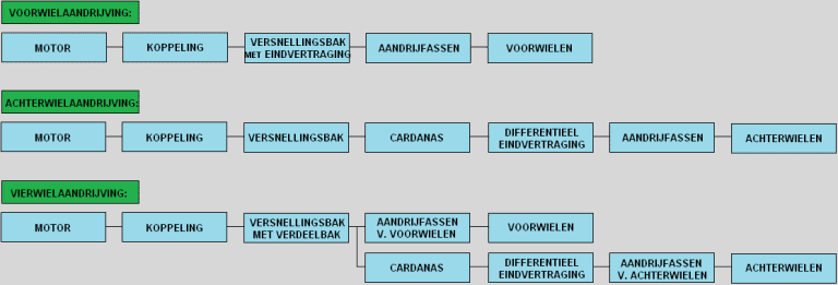
Below is a block diagram showing how the drive from the engine to the wheels is achieved in front-wheel, rear-wheel, and all-wheel drive. For more information, see the page types of drive.

Single and Double Reduction:
Manual transmissions are divided into two groups, namely single and double reduction. Reduction is another term for transmission. So it actually means “single and double” transmission. Below is shown what is meant by it.
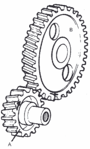
Single Reduction
The gears of the input and output shafts are directly connected.a0

A: Input shaft (input shaft, from the engine)
B: Output shaft (main shaft)

Double Reduction
First gear is engaged; the driving forces in first gear go from A to B and from C to D.
A force is applied to gear A via the input shaft. This gear is directly connected to gears B, D, and E. Since first gear is engaged, the synchronization device couples the output shaft to gear D (see blue arrows). From gear B, the driving forces exit the transmission through the output shaft. The output shaft drives the differential, which may be inside the transmission (in front-wheel drive cars) or may be mounted elsewhere as in a rear-wheel drive car. More is explained on this later on this page.


A: Gear input shafta0(input shaft, from the engine)
B, C & E: Gears on the secondary shaft
D & F: Gears on the output shaft (main shaft)

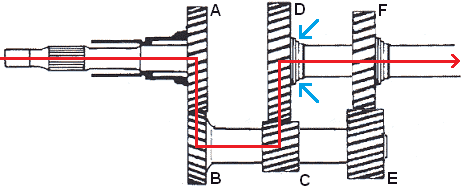
Second gear is engaged. The synchronization device is disconnected from gear D and coupled to gear F (see blue arrows). At that moment, gear D still rotates, but is not coupled to the output shaft. Gear F is, so the driving forces now go from A to B and from E to F.

Since gears C and E have different dimensions, the gear ratios have changed. This results in a drop in engine speed after coupling at the same vehicle speed.

a0

Transmission in Longitudinal or Transverse Direction:
The image shows a diagram of a rear-wheel drive car. The engine block is placed longitudinally (in the length) and the transmission is equipped with double reduction. The final drive (the differential) is placed at the rear axle and drives the rear wheels. This is the type of drive commonly used by BMW, for example.

This image shows a diagram of a front-wheel drive car. The engine block is placed transversely (in the width) and the transmission is equipped with single reduction.
The driving forces enter the input shaft (the input shaft) and are transmitted through the engaged gears to the output shaft. The differential is integrated into the transmission housing. This type of drive is used, for example, in a Volkswagen Golf and a Ford Focus (and of course many other brands!).

The image shows a diagram of a front-wheel drive car. Here, both the engine block and the transmission are placed in the longitudinal direction. The engine block is located in front of the front axle and the transmission behind the rear axle. The differential is mounted at the height of the drive shafts. This system has been used in older models of the VW Passat, Skoda Superb, and Audi A4. The newer models now feature a transversely mounted engine block (thus the situation below).

Gears and Speeds:
With the different sizes of the gears, different gear ratios can be established. These gear ratios are called speeds. When a large gear is driven by a small gear, the small gear can make, for example, 3 revolutions, while the large gear rotates only once. The gear ratio is then 1:3. The reduction and the increase in force are then 3 times greater. When the small gear has 20 teeth, the large gear will have 60 teeth.

Below are the different speeds that can be engaged. You can see that with each speed, the right gear of the upper shaft (the primary shaft) becomes progressively smaller in gears 2 and 3. The gear on the right side of the secondary shaft becomes progressively larger. This increases the gear ratio steadily, which is the ultimate goal for shifting to another speed.

First Gear:
The driving force enters at the arrow on the left on the input shaft. The driving force is directly transferred to the gear of the secondary shaft. The secondary shaft is the lower shaft. The smallest gear on the secondary shaft is coupled to the second last gear of the output shaft. Due to the dimensions of the gears, the output shaft rotates much slower than the input shaft. This results in the greatest reduction. The first gear has the greatest reduction so that it is possible to accelerate from a standstill with a lot of torque multiplication.

Second Gear:
The gears on the left remain engaged. The driving force goes via the third gear of the secondary shaft to the third gear of the output shaft. The output shaft still rotates slower than the input shaft. So there is still a reduction. However, the reduction is now smaller than in first gear, so at the same engine speed, a higher vehicle speed can be achieved than in first gear.

Third Gear:
The driving force goes via the second gear of the secondary shaft and the second gear of the output shaft. The output shaft still rotates slower than the input shaft. The reduction is now again smaller than in second gear, so also now at the same engine speed, a higher vehicle speed can be achieved than in second gear.

Fourth Gear:
This is called direct drive. The driving force goes directly from the input shaft to the output shaft. The engine torque is then transmitted 1 to 1 to the wheels. The transmission essentially does not participate now.
In a five-speed transmission, the fourth gear is always direct drive. However, in a six-speed transmission, the fifth gear is direct drive.

Fifth Gear:
In fifth gear, the two rear gears are connected to each other. Here, the largest gear of the secondary shaft is coupled to the smallest gear of the output shaft. This is called ‘overdrive’. The output shaft now rotates faster than the input shaft.
Gears 1, 2, and 3 are reductions; the input shaft rotates faster than the output shaft. In fourth gear, the input shaft rotates at the same speed as the output shaft (direct drive). Thus, in this 5th gear, there is a true acceleration, because in this gear alone of all gears, the output shaft rotates faster than the input shaft. On the freeway, this results in lower engine speed. When acceleration is needed, often it is necessary to downshift to a lower gear.

Reverse:
When selecting reverse, an extra gear is placed between the gears of the secondary and output shafts. Normally, if the lower gear rotates counterclockwise, the upper gear mounted against it will rotate clockwise. If you place yet another gear next to that clockwise-rotating gear, it will rotate counterclockwise again. This is effectively done in the transmission. The input shaft simply drives in the usual manner, and the extra gear causes the output shaft to rotate in the opposite direction.

Conclusion:
It has been explained above that by coupling gears of different sizes, a different gear ratio (i.e., speed) is created and how the drivetrain runs then. Below is explained how the engagement and disengagement of the gears works when the gearstick is operated.

Transmission Operation:
When the gear stick is moved inside the interior, the cables or rods (depending on the type of transmission/mechanics) are moved that go to the transmission.
The image below shows that the selector drum can move back and forth. This space is indicated in pink. The selector drum operates the shift fork. The shift fork uses the shift ring to press the synchromesh ring against the gear. When shifting to the next gear, the selector drum moves back, setting the shift fork to the neutral position. By engaging another gear, the same shift fork is moved by the selector drum the other way to engage the other gear (e.g., from third to fourth gear) or another selector drum is used to operate the other shift forks.

In the transmission, there are multiple selector drums. Each selector drum can engage or disengage two gears. The operation of the different selector drums is done by moving the gearstick left and right. The image below shows the H-pattern of the gears.

When the driver wants to engage first gear, he will first move the gearstick from the middle (N for ‘neutral’) to the left. The shift shaft will engage with the teeth of the selector drum of the first and second gear.

By moving the stick upward (to first gear), the selector drum is pushed backward (in the image to the top right). This connects the shift fork to the gear of the first gear and the shaft.
To shift to second gear, the stick must be moved downward (to neutral). The shift fork disconnects the gear from the shaft. By moving the stick further down, the same shift fork connects the other gear with the shaft; the second gear is now engaged. This selector drum therefore shifts the shift fork between the first and second gear.

To shift to third gear, the gear of the second gear must first be disconnected from the shaft. To do this, the stick must first be moved upwards again (to the neutral position). Then the stick must be moved to the middle of the H-pattern. By moving the stick from the left to the middle, the selector drum of the third and fourth gear is engaged. Pushing the stick forward and backward will cause the shift fork of the third and fourth gear to move forward or backward to engage these gears.
When shifting up to fifth gear, the stick is pushed all the way to the right. Here, the selector drum of the fifth gear and reverse is coupled. To select fifth gear, the selector drum is pushed forward so that the shift fork can connect the gear with the shaft.

The image shows a shift mechanism. This cable-operated mechanism is used in a car with a transversely mounted engine block. The levers 1 and 2 are moved by the pushing or pulling movement of the cables, moving the shift forks through a so-called shift tower.

Synchronization Device:
When no synchronization device is used, the gears, due to the difference in speed, will not engage smoothly or will engage with grinding. To ensure the smooth coupling of the gears, synchromesh rings are used. The synchromesh rings ensure that the rotational speeds of the shaft and the gear are the same when engaged. All gears (1 through 5 or 6) are synchronized, often except for the reverse gear. You might notice this because the gear will sometimes grind when engaging the reverse gear. Sometimes reverse gears are synchronized.

The gears for the speeds that are not engaged rotate freely around the output shaft. Engaging a gear means coupling a freely rotating gear to the output shaft. When a gear is engaged, the rotational speed of the output shaft must match the speed of the gear to be engaged. The synchromesh ring is connected to the output shaft along splines and therefore rotates at the same speed as this output shaft. The gear to be engaged has a different speed than the output shaft, so also a different speed than the synchromesh. As the shift fork moves, it takes the synchromesh with it and the conical part of the synchromesh ring is pressed against the inner conical surface of the gear. The conical parts of both parts are pressed against each other, causing the friction between the conical surfaces to be equalized. When there is no longer a speed difference between the gears, the shift clutch can be pushed through so that the teeth interlock and the gear is engaged without grinding. The synchronization device works not only when engaging the gears but also when shifting and downshifting.

It is very bad for the synchromesh rings to shift very quickly, i.e., to push the shift stick very hard into gear. The synchromesh then does not have time to synchronize. Therefore, it is best when shifting to gently press the stick against the resistance and only push through when it almost automatically slips into its gear.

A synchromesh ring is a wear part. During shifting, friction occurs, so the part will wear over time. With normal use, the synchromesh ring can last a car’s lifetime, but with improper use or sporty shifting, the synchromesh rings will be worn prematurely. The distance (3) between the synchromesh ring and the gear in the image below will become smaller. This is because the synchromesh ring wears out at the contact point where it touches the gear. This section is indicated with distance 1.

When the transmission is disassembled, the synchromesh rings can be checked for wear. With a feeler gauge, the distance between the synchromesh ring and the gear can be measured. The gear must not be engaged during this measurement. With a worn synchromesh ring, the distance between the synchromesh ring and the gear becomes smaller.
The manufacturer of the car or transmission specifies in the workshop documentation what the wear limit of the synchromesh ring is. If the measured value is smaller than the maximum wear value in the workshop documentation, it must be replaced.

Disassembling the Transmission:
This paragraph describes how a transmission can be disassembled. This provides a good picture of what the interior of the transmission actually looks like and how the parts in the transmission can be replaced. This involves a transmission of a rear-wheel drive car with a longitudinally placed engine.

In the displayed transmission, several bolts at the rear can be dismantled. Subsequently, the rear can be slid off. Of course, the transmission oil should be drained first before parts are dismantled.

The interior with the shafts and gears is fixed at the back. The entire interior comes out of the transmission housing during dismantling.

Inside (on the right side of the hole through which the input shaft is mounted in assembled condition) the bearing of the secondary shaft can be seen.
On the left side of the hole of the input shaft, five holes are visible. In these five holes are the four ends of the selector drums.

The image shows the input shaft, the gears, and the selector drums with the shift forks. When shifting, the respective selector drum rotates and moves so that the shift fork operates the synchromesh ring of the gear to engage the speed.

After the clamped pins or screws with which the shift forks are connected to the selector drums have been disassembled, the selector drums can be slid out. This leaves the shift forks loose. The shift forks can be slid off the shafts.

In the image below you can see what the gears look like. When gears or synchromesh rings need to be replaced, the shafts need to be removed from the other side of the transmission housing. The gears and the synchronization device need to be pressed off the shafts. The new parts then need to be pressed onto the shaft again.

To check if the synchromesh rings are still in good condition, the distance between the gear and the synchromesh ring must be measured. If the distance is greater than the maximum value specified by the manufacturer, the synchromesh ring is worn out. The synchromesh ring must be replaced. How the measurement should be performed is described under the paragraph “synchronization device” on this page.

Constant Mesh:
In a Constant Mesh transmission, the gears are ‘constantly’ engaged with each other. The gears are mounted on the output shaft and are connected using shift sleeves and dog clutches. In the explanation above, the Constant Mesh transmission has been discussed.
In the image below, the right shift sleeve moves to the right to engage first gear and to the left to engage second gear.

Sliding Mesh:
These are English words for ‘sliding’ and ‘engaging’. In this type of transmission, gears are shifted to engage a particular speed. This is still used today for reverse gears but is actually never used in modern transmissions anymore, so we won’t go too far into it. The teeth are straight with a slanted edge at the ends. With this type of transmission, you will always hear grinding when shifting because it is naturally not synchronized.

Gear Ratios:
The gear ratios in the transmission must be accurately calculated and constructed. In the image below, the vehicle speed is shown on the X-axis and the force on the wheels on the Y-axis. It can be seen that the 1st gear has a lot of force at the wheels but stops at a low vehicle speed. Each successive gear has less force at the wheels and a higher speed range.
Click here to go to the Gear Ratios page, where via the geometric series and the corrected geometric series (the Jante series) with the K-factor, all gear ratios are calculated.
Per transmission, the maximum vehicle speed can then also be calculated.

  • Home
  • About
  • Disclaimer
  • Copyright
  • Statistics
  • Projects
  • Workshop
  • Search
  • Home
  • About
  • Disclaimer
  • Copyright
  • Statistics
  • Projects
  • Workshop
  • Search

Copyright 2025 © MVWautotechniek.nl
Designed, written and hosted by Marco van Wijk