Introduction:
An LED is a widely-used semiconductor component for emitting light. LED stands for: Light Emitting Diode. Since its invention in 1962, LEDs have primarily been used as indicator lights and for signal transmission. Technological advances since the late 1990s have made it possible to produce LEDs that serve as light sources for everyday use. In automotive technology, LEDs are extensively employed for instrument lighting (dashboard), exterior lighting (taillights), or main lighting (in headlights) due to the following advantages over incandescent and halogen lamps:
- low energy consumption: LEDs use significantly less energy than other types of lamps with equal light intensity. LEDs have a very high efficiency of up to 80%;
- safety: incandescent lamps take about 200 ms to bring the filament to temperature and emit light. LEDs do not have a warm-up phase, meaning they reach their light intensity faster (in less than 1 millisecond). When used as brake lights, LED lamps enable braking to be noticed earlier, positively affecting stopping time;
- low heat development: as LEDs generate minimal heat, lamp housings can be made smaller and cheaper materials can be used, which are less resistant to thermal stress;
- long lifespan: an LED lasts approximately the entire life of a vehicle. If LEDs are defective, the cause is often found elsewhere, such as a break in the circuit board or incorrect control. However, the brightness of an LED may diminish with a certain number of operating hours.
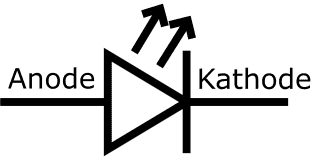
The adjacent image shows the symbol of the diode, with additional text above the “anode” and “cathode” sides. The symbol of an LED is almost identical to that of a diode, but it includes two upward-facing arrows indicating light emission. The current direction, as with the diode, is in the direction of the arrow. The vertical line represents the reverse direction. If the current flows in the arrow’s direction (left to right) through the LED, it will light up. Conversely (right to left), it will block and not light up.
Operation of an LED:
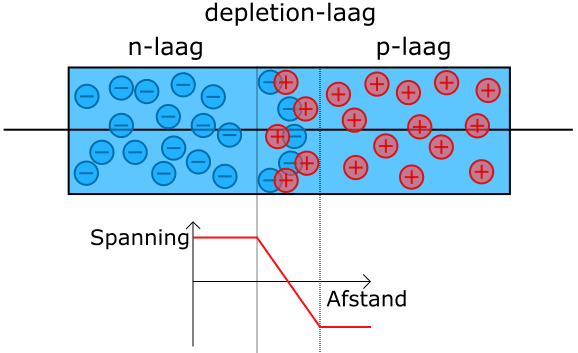
Like a “normal” diode, an LED is made up of two semiconductor layers:
- the negative layer (n-layer) contains an excess of electrons;
- the positive layer (p-layer) has a shortage of electrons.
The lack of electrons in the p-layer can be seen as an excess of positive holes. In the pn-junction (depletion layer), the electron surplus in the n-layer fills the holes in the p-layer. No current flows yet, so the charge in the np-junction is neutral.
To allow current to flow through the diode, the internal voltage of the depletion zone must first be overcome. This is known as the diffusion voltage or threshold voltage of the diode. As the voltage is increased, the electron current can flow from the n-layer to the p-layer. However, in the depletion layer, some of these electrons are captured by the holes. These electrons release part of their energy in the form of light flashes. The generated light can escape through the thin p-layer. Light intensity is determined by the current strength: the stronger the current, the more intense the light.
The transition of valence electrons from the negative to the positive layer results in the light the diode emits.
Conduction Voltage in Relation to the Color of the LED:
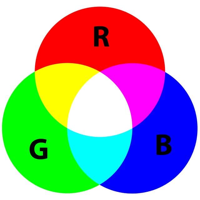
LEDs come in three colors: red, green, and blue. By mixing these three primary colors, other colors can be obtained. The composition of materials in the n- and p-layers determines the energy levels of the electrons and holes.
- Low-energy electrons convert less energy into light emission than high-energy electrons;
- Red light has less energy than blue light;
- Red is produced by low, and blue by high-energy electrons.
White LEDs cannot be produced directly. By adding an extra fluorescent layer to a blue LED, part of the blue light is converted into yellow light. The mixture of blue and yellow light is perceived by the human eye as white light. By adjusting the blend ratio between this yellow and blue light, warm or cool white light can be emitted.
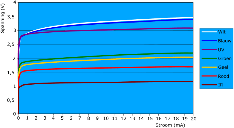
The characteristic shows the voltage built up in the depletion zone, and thus the conduction voltage of the respective color LED. When current is passed through an LED, a virtually constant voltage drop occurs.�a
Control Methods:
In automotive technology, LEDs can be controlled with a series resistor or in series connections to achieve the desired control voltage.
LED with Series Resistor:
Directly connecting an LED to the positive and negative terminals of a battery would cause it to fail immediately. A series resistor must always be placed in series with the LED.
The value of the series resistor is determined by two factors: the current and supply voltage. A red LED emits light once the operating voltage of 1.5 volts is reached and about 20 mA flows through it.
The supplied voltage depends on the application. In automotive settings, this can be 5, 12, or 24 volts. Ohm’s Law can be used to determine the required resistor. Subtract the operating voltage from the supply voltage and divide this by the current.
- For a supply voltage of 5 volts, a red LED requires a series resistor of (5 – 1.5) / 0.02 = 175 ohms.
- For a supply voltage of 12 volts and a red LED: (12 – 1.5) / 0.02 = 525 ohms (a resistor one factor higher).
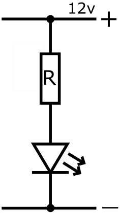
The LEDs with series resistors are mainly found in retrofitted LED lighting (retrofit). The quick on and off times and brightness of an LED can be reasons to replace incandescent lamps with LEDs. However, for energy efficiency, it is not always beneficial as the series resistor also causes power loss, which can be as large as the power dissipation of the original lamp in some cases.
LEDs in Series:
By connecting LEDs in series, no or only a low resistance series resistor is needed. The internal resistance of the LEDs themselves ensures the supply voltage is distributed over the LEDs in the series connection. The more LEDs placed in series, the smaller the series resistor can be. The image shows six LEDs connected in series and two rows parallel.
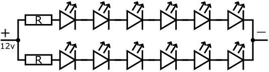
Series-connected LEDs are found in taillight units or third brake light units. This is a commonly used control method in automotive technology.
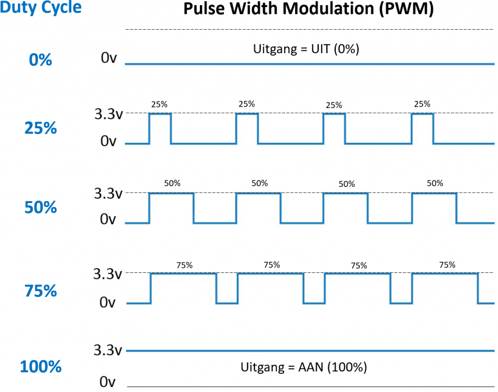
Adjusting Light Intensity:
With a microcontroller, LED control can be regulated with a pulse. This is known as: Pulse Width Modulation (PWM).
The duty cycle determines the time the LED is on. By rapidly alternating the on-off pulses between 3.3 and 0 volts, the LED lights up at a lower brightness.�a
This control method is similar to a multi-function incandescent lamp, such as:
- 50% brightness with lights on;
- 100% brightness with brake light on.
In a practical setup with an Arduino, one can experiment with the PWM control of the LEDs on the Arduino or externally connected LEDs (equipped with series resistors).
LEDs with Multiple Colors:
With the three primary colors red, green, and blue, all colors can be created. This can be effectively utilized by combining two or three LEDs. Below are three principles used to obtain multiple colors through an electrical circuit.
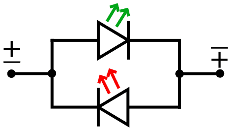
Two-Color LED:
The schematic shows two parallel-connected LEDs with reversed blocking and conducting directions. Current direction determines which LED lights: green (top) or red (bottom). The polarity is reversed by an external circuit or ECU.
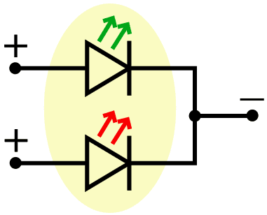
Three-Color LED:
This schematic also shows two parallel-connected LEDs. A supply voltage can be applied to one of the two LEDs (green or red), or both simultaneously. If both are powered, color mixing occurs and the red and green LEDs appear yellow.
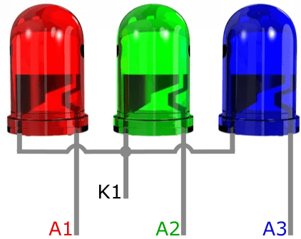
RGB-LED:
With RGB-LEDs, three LEDs of their respective colors are housed in a single package. The colors can be individually controlled. To control the RGB-LED, three PWM controls are required, generating a variable on/off ratio on each power pin. Alongside the various colors, light intensity can also be set.
The next image shows three LEDs each with their own Anode connection (A1 to A3) and a common Cathode.