Ignition switch:
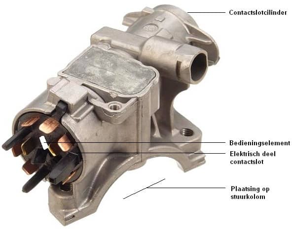
The image below shows the rear side of an ignition switch. The ignition switch cylinder is located at the front and, using the actuator behind the cylinder, moves the electrical part of the ignition switch.
Because the electrical part (also called the contact block) moves relative to the housing, various switching circuits are possible. The key position indicates which contacts in the electrical part are connected (for example, when the constant power wire (terminal 30) is connected to the starter wire (terminal 50b), the engine will start. If the key is released, terminal 15 (ignition) remains switched on. When the key is turned fully to the left (the off position), all contacts are disconnected, and the engine and ignition are switched off).
When the key is removed from the ignition and the steering wheel is turned, the steering lock is engaged. An iron pin moves from the ignition switch into a notch in the steering column. To disengage the steering lock, the ignition key must be inserted and turned while applying light pressure on the steering wheel.
The operation of the lock cylinder is described on the lock cylinder page.
Nowadays, ignition switches are increasingly being used without a lock cylinder and operate fully electronically with a plastic chip or key.
Electrical part of the ignition switch:
Behind the lock cylinder is the electrical part, also called the “contact block.” This part essentially ensures that the movement made with the key is converted into voltage on the correct wires; in other words, selecting the accessory position and starting.
The electrical part is often secured with a small screw, making it relatively easy to remove from the ignition switch housing when a repair is needed.
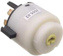
The image on the right shows the front of the contact block. In the center is a yellow, round, rotatable part with a horizontal slot. When the key is inserted into the ignition switch, the end of the key fits into this slot. When the correct key is inserted into the lock cylinder, it can turn thanks to the wafers inside the ignition switch. What you are actually doing is rotating the yellow part inside the contact block. Internally, the switching contacts (where the connector is attached at the back) are connected to each other. This is explained in more detail in the diagram in the next section.
It may happen that the car can no longer be started. In that case, the contact block may be internally defective. To check this, you can measure the control voltage on the small wire to the starter motor.
In older cars, it was sometimes possible to remove the connector from the contact block and then manually bridge certain contacts with a separate wire. Or to rotate the yellow part with a screwdriver as shown in the above image. This is how cars could be started and moved. Car theft often occurred this way.
To prevent this, every car nowadays is equipped with an immobilizer. The transponder serial number in the key is compared to stored values. If these do not match, the engine will shut down immediately after starting. It is therefore no longer possible to start and run the car simply by bridging wires or operating the contact block alone.
Wiring diagram of ignition switch with load reduction relay:
The diagram below is of the ignition switch. It shows the component codes such as CS for the ignition switch and RX for the load reduction relay. Terminal designations 15, 30, 31, 50, and 75 are also shown here.
When the ignition switch is put in position 1, terminal 15 is connected to terminal 30. This turns on the ignition and supplies power to consumers such as the interior equipment. During starting, terminal 50(b) is supplied with voltage, causing the starter motor to run. When the ignition switch is turned to position 0 but the key has not yet been removed from the lock cylinder, voltage remains present at terminal 75. Consumers such as the radio are connected to terminal 75. In the vehicle shown in this diagram, the radio will therefore remain on when the ignition is off and the key has not yet been removed from the lock cylinder.
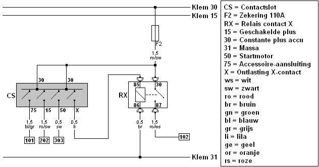
The function of the load reduction relay contact X (in English, called the “load reduction relay”) is to switch off consumers that require high voltage and current, such as the blower (interior fan), the radio, low beam headlights, rear window defroster, seat heating, etc., at the moment the engine is started. During starting, switch x in the ignition switch (as shown in the diagram’s current state) opens. The voltage to the electromagnet (between terminal 85 and 86 on the relay’s control circuit) is interrupted. As a result, there will be no main current flowing from terminal 30 to 87, which means the consumers, which are connected to wire number 102 in another diagram, are temporarily switched off. At that moment, more current is available for the starter motor than if other consumers were still using significant current. That is why this component is called a load reduction relay.
When the ignition key is turned back after the engine has started, switch X in the ignition switch closes again. Relay RX is re-energized, so that the consumers again receive power and current.