Introduction:
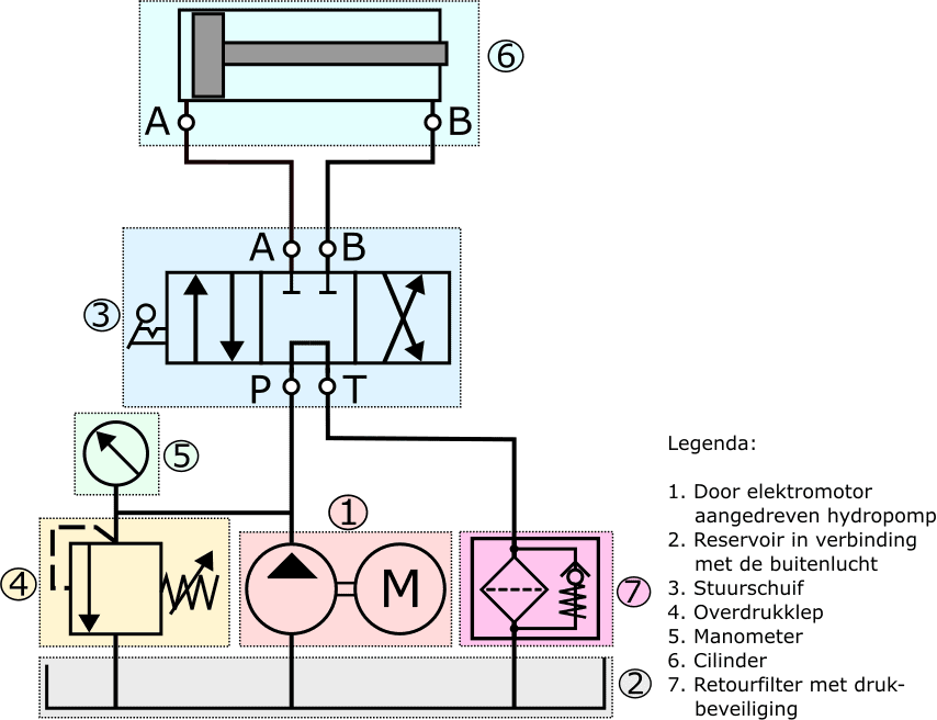
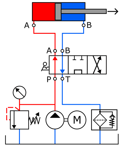
The hydraulic pump (1) draws oil from the reservoir (2) and pumps the oil into the system. After the oil passes through the control valve, the pressure relief valve, or the cylinder into the return line, it flows back pressure-free to the reservoir.
The hydraulic pump in the illustration is driven by an electric motor, which regulates mechanical power in the form of torque and speed. The hydraulic pump converts this into hydraulic power. The pump output/flow rate depends on the speed and displacement of the hydraulic pump.
Most hydraulic pumps operate based on the displacement principle. The types can be classified as:
- gear pumps;
- vane pumps;
- piston pumps.
The following sections delve further into this.
Gear Pump:
The gear pump is used in hydraulic systems with a low working pressure of up to 140 to 180 bar. Due to its simplicity, low cost, and reliable properties, the gear pump is one of the most commonly used hydraulic pumps found in hydraulic applications.
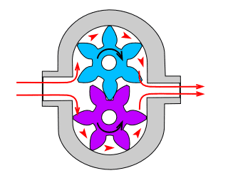
In the gear pump with external gearing, there are two gears that move in opposite directions. One of the gears is externally driven, causing it to drive the other gear.
- suction side: the gears separate on the left side. Due to the increase in volume in the cavities, a vacuum of approximately 0.1 to 0.2 bar occurs, causing oil to be drawn in. The gears transport the oil via their outer circumference to the discharge side;
- pressure side: here, the gears intermesh. The oil in the discharge line is displaced into the system.
The pressure on the discharge side depends on the resistance that the oil encounters in the hydraulic circuit.
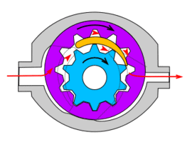
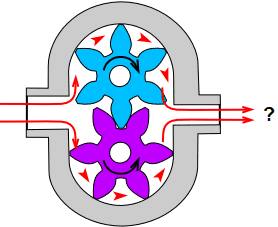
The gear pump with internal gearing contains a crescent-shaped separator. The inner (blue) gear is externally driven and thereby takes the outer (purple) ring with internal gearing in the indicated direction of rotation. As in the pump with external gearing, a vacuum occurs when the space between the teeth increases. The pump thus draws oil from the reservoir. When the gears intermesh, the oil is displaced into the system. The crescent-shaped separator ensures a separation of the suction and discharge sides.
This type of hydraulic pump can achieve pressures of up to 300 bar. The pump has a uniform output and produces very little noise.
Gear pumps always have a fixed displacement. At a constant drive speed, the output is constant. On the outer circumference of the gears, the gear heads run closely along the pump housing providing radial sealing. In the center of the pump, where the gears intermesh, there is also a certain sealing between the gear flanks and the bearing plate. There will always be a slight oil leakage between the sealing surfaces.
The gear pump is found in the following application areas:
- vehicle technology (e.g., automatic transmission);
- machine building;
- agricultural hydraulics;
- aviation hydraulics.
Vane Pump:
The vane pump has a rotor with radially placed vanes. On the suction side (blue), the volume increases causing a vacuum and oil is drawn in. On the discharge side (red), the volume decreases, overpressure occurs, and the oil is pressed into the line.
The rotor is eccentrically positioned relative to the cam ring, allowing the output to be adjustable:
- In the left image below, we see a pump with zero output at zero cm³ per revolution. The pump then delivers no more oil;
- The right image shows the adjusted cam ring providing maximum output.
The vane pump is found in the following application areas:
- construction and road-building machinery;
- machine tools;
- aviation hydraulics;
- mobile hydraulics.
Piston Pump:
The axial piston pump is found in systems where higher pressures occur (>250 bar) and greater powers are transmitted because the efficiency of this type of hydraulic pump is high. Piston pumps are categorized into radial and axial piston pumps.
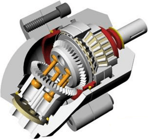
Axial Piston Pump:
The input shaft of the axial piston pump drives a swash plate. The swash plate is set at a specific angle and converts the rotational movement of the input shaft into a reciprocating movement of the pistons. The pump is equipped with suction ports and pressure valves, allowing the direction of rotation of the input shaft to not affect the flow direction of the hydraulic oil.
By adjusting the angle of the swash plate, the stroke of the pistons can be influenced. The steeper the swash plate is set, the greater the piston stroke, thus displacing more oil. This technique is used in air conditioning compressors.
The following images show the axial piston pump.
Radial Piston Pump:
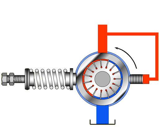
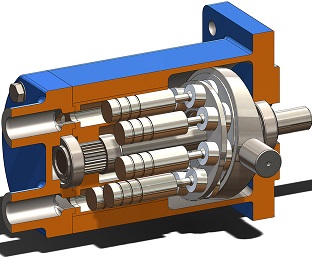
Radial piston pumps are primarily found in heavy-duty drives on ships, such as dredging installations, winch drives, and rudder drives, as well as in machine building. These pumps have a short installation length, are suitable for high operating pressures (700 bar), and deliver high torque at a low speed.
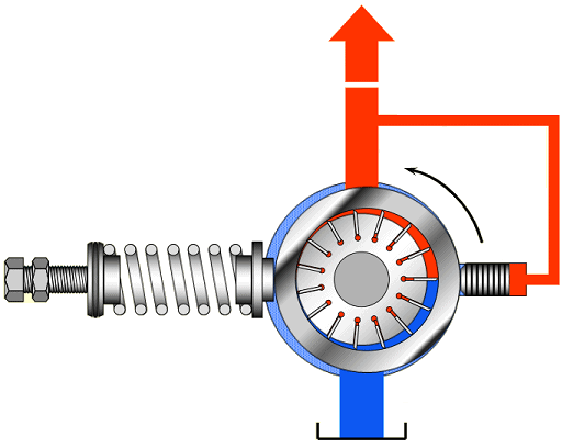
The radial piston pump in the following image contains five radially positioned pistons in a star shape relative to the drive shaft. As the ring is eccentrically designed, a radial piston movement is created. A distribution plate rotating with the drive shaft ensures that each cylinder is connected to the suction or pressure line at the right moment.
Introduction to Hydraulic Pump Calculations:
To move the piston with the correct force and speed, the hydraulic pump must deliver sufficient pressure and fluid flow that is large enough. The greater the load the cylinder must handle, the higher the demands placed on the hydraulic pump.
Below are three sections where we calculate the flow rate, the required pressure, and the required power, taking efficiency into account, for the hydraulic pump in the accompanying diagram.
- pump displacement (V) = 15 cm³ / rev;
- pump speed (n) = 1200 rev / min;
- system pressure: 50 bar.
Calculate Hydraulic Pump Flow Rate:
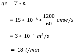
The amount of hydraulic oil that a hydraulic pump displaces depends on the speed and displacement of the pump. The data is listed in the section above.
In the formula, we convert the speed per minute to seconds by dividing the number by 60. In the final step, we convert cubic meters per second to liters per minute by multiplying the answer by 60,000.
Calculate Required Hydraulic Pump Power:
The hydraulic pump must provide hydraulic power to transport fluid to the cylinder and move the piston.�a0
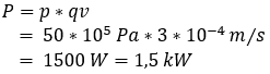
With the data from the “Introduction to Hydraulic Pump Calculations” section and the answer from the previous section, we can calculate the required power of the hydraulic pump. For clarity, they are summarized here again:
- pump displacement (V) = 15 cm³ / rev;
- pump speed (n) = 1200 rev / min;
- system pressure: 50 bar;
- flow rate: 18 liters per minute.
We convert the system pressure of 50 bar to Pascals and the flow rate to cubic meters per second. This is noted in scientific notation.
Calculate Required Drive Motor Power:
The pump shaft (input shaft) provides the mechanical power, which usually comes from an electric or combustion engine. The hydraulic motor converts the mechanical power into hydraulic power. Energy conversion always involves losses. Therefore, the drive motor must provide more power to allow the hydraulic pump to deliver its required power.
In this example, we assume an efficiency of 90%.
Related page: