Operation of the four-stroke gasoline engine:
The gasoline engine was invented in 1876 by Nikolaus Otto and is therefore also called the “Otto engine.” In this mixture engine, chemical energy is converted into mechanical energy. Air, gasoline, and a spark are required for this. There are various techniques to obtain as much air and a controlled amount of fuel into the cylinder as possible. A high filling rate is achieved using variable valve timing or forced induction. The fuel injection can be realized by two different injection systems; direct and indirect injection. More on this later.
The operation of the gasoline engine, despite all innovative techniques, always comes down to the same principle. During a complete work cycle, the combustion of the gasoline results in the rotation of the crankshaft. The crankshaft is attached to the drivetrain. The different steps of the work cycle are divided into four strokes; the intake, compression, power, and exhaust stroke.
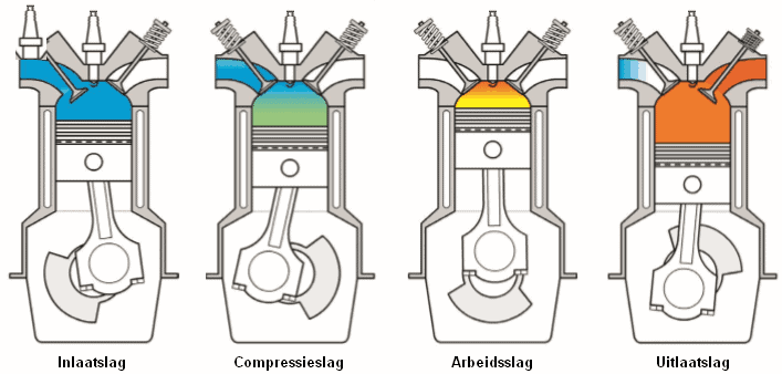
Intake stroke: the piston moves from the top dead center (TDC) to the bottom dead center (BDC). The intake valve opens simultaneously with the downward movement of the piston. This allows the piston to draw air into the cylinder. The air comes from the intake manifold and the air filter. Depending on the type of engine, fuel is also injected by an injector. Once the piston reaches the BDC, the intake valve closes.
Compression stroke: the intake and exhaust valves are closed, and the piston moves up to the TDC. The mixture of air and fuel is compressed.
Power stroke: several degrees before the piston reaches the TDC, the spark plug produces a spark. Since gasoline is highly explosive and sufficient oxygen is present, combustion occurs. The resulting force pushes the piston down.
Exhaust stroke: after the power stroke, the piston reaches the BDC. The exhaust valve opens, and the piston moves back up; the burned gases (exhaust gas) are expelled.
As soon as the piston reaches the TDC, the exhaust valve closes, and the intake valve opens. In this situation, both valves are slightly open; the speed at which the exhaust gases flow out of the cylinder affects the incoming air along the intake valve. Air is already being drawn in while the piston is not yet moving toward the BDC. This is also known as “valve overlap.”
The cycle process is described on the page Seiliger process. The animation below shows the four-stroke process of a gasoline engine.
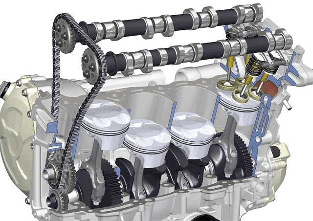
The animation shows the four-stroke process of only one cylinder. In automotive technology, engines are often equipped with four cylinders. Three, five, six, and eight cylinders are also frequently used. Some manufacturers also utilize ten, twelve, or even sixteen cylinders. The power strokes of the cylinders follow each other: in a four-cylinder engine, two power strokes occur during each crankshaft rotation. The order is important; this is described in the following paragraph.
Intake stroke (1)
Compression stroke (2)
Power stroke (3)
Exhaust stroke (4)
Ignition sequence (work diagram):
Engines always have a fixed ignition sequence. During each power stroke, the combustion force is transmitted to the crankshaft via the piston. The working forces must be optimally distributed during the rotation of the crankshaft, otherwise uneven movements can occur (resulting in additional vibrations and irregular operation).
In a four-cylinder engine (both gasoline and diesel), the ignition sequence is 1-3-4-2. This means that the power stroke first occurs in cylinder 1, then a half crankshaft rotation later in cylinder 3, another half rotation later in cylinder 4, and yet another half rotation later in cylinder 2. The crankshaft has then rotated twice (720 degrees). This constitutes a complete combustion cycle.
The work diagram below shows which cylinders are engaged with which stroke; at the moment cylinder 1 is in the power stroke, cylinder 4 is in the exhaust stroke. For reference; the red arrows indicate the timing of the spark plug.
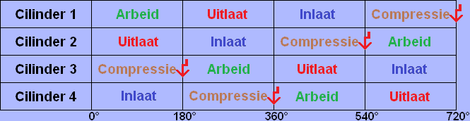
The image is of a four-stroke engine where the first cylinder (determined from the timing side) begins its intake stroke. The piston then moves from top to bottom.
In the above work diagram, it is shown that cylinder 2 must begin the compression stroke. This is correct because it is still at the BDC (bottom dead center). Cylinder 3 begins the exhaust stroke, and cylinder 4 begins the power stroke (at this moment, the spark from the spark plug occurs, causing the piston to be pushed down by the force of the combustion of the gasoline-air mixture).
Related pages: