Engine Management with Self-Diagnosis:
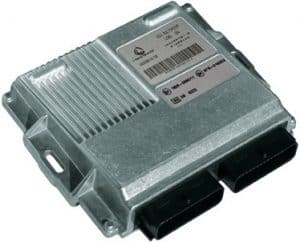
Every modern car has an engine management system. This is the term for the software embedded in the ECU (Electronic Control Unit). All sensors and actuators on the engine are connected to the ECU via wiring harnesses. Click here for more information about the control units and the networks in the car. The main functions of the ECU are to control the ignition and injection, aiming for the least possible emissions. There are many other functions interconnected, all influencing each other. These will be discussed below.
The ECU processes incoming data (from the sensors), processes it, and then controls the actuators. An example of a sensor is the oxygen sensor. When the oxygen sensor measures a too high oxygen content in the exhaust gases, it will forward this to the ECU. The ECU then knows that the mixture is too lean (too little fuel = too much oxygen in the exhaust gases = thus too lean). The ECU will then adjust the injection and ignition until the oxygen sensor provides the correct signal.
When a sensor provides an impossible reading (such as the coolant sensor showing an unmeasurable value), or detects that the wiring has a short circuit with positive or ground, the ECU will automatically store this as an error code. The advantage of the advanced software is that the incorrect signal is internally blocked. For example, the ignition and injection are not adjusted based on the incorrect temperature since the ECU has already recognized that this signal is incorrect.
However, the ECU will fully control the cooling fan because the correct temperature can no longer be measured. As a precaution, additional cooling is provided. A yellow engine light will come on the dashboard. The car will then need to be diagnosed. Click here to go to the OBD page where much information is provided about reading errors and other possibilities of the diagnostic equipment.
Another example is a coil that has failed. The fuel will enter the catalytic converter unburned and may still burn there due to too high a temperature. The crankshaft sensor will register an RPM fluctuation due to the missed combustion. The cylinder misfire position is recognized. Thus, the injector of the cylinder with the defective coil is stopped. The engine is now in limp mode and will run with one cylinder less. The engine warning light will illuminate. It will become clear on diagnosis which cylinder is misfiring.
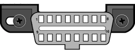
To diagnose, the computer’s diagnostic plug (shown in the image) is connected to the OBD plug. This OBD plug is usually found at the bottom of the dashboard, near the footwell (by the pedals). The plug can also be hidden in other parts of the dashboard or behind ashtrays. By connecting the plug with the diagnostic tool, the error codes are transmitted to the computer.
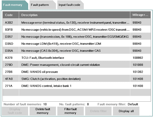
When the car is diagnosed, the ECU will provide an error code to the diagnostic computer. This error code (OBD fault code) is often the same for each brand. These codes can be displayed with a diagnostic device. The ECU records the error code and also stores the following information:
- When the fault occurred first and last.
- How often the fault has recurred.
- Whether it is a permanent or (sometimes) recurring fault.
Error codes are not always the same for every brand. Sometimes codes are brand-specific. By searching the error code on Google, the meaning can often be found.
Advanced diagnostic equipment links a text to the error code. Basically, the code is translated into text. For instance, the code P0267 will be linked to the text: “Coolant temperature sensor improbable signal; short circuit to positive.” First occurred at mileage ……km, frequency 120, sporadic occurrence. It is now clear that either the sensor has an internal defect, or the sensor signal cable is short-circuited with a positive cable. This has occurred 120 times in total and is not permanently present. It may mean that due to cable movement, the short circuit occurred 120 times and then disappeared again. It is up to the technician to find out where the fault is.
When the fault is resolved (e.g., after repairing the cable), the fault can be erased. A code is then sent to the ECU with the test equipment, which then understands that the fault must be written out of memory. If the cable is not repaired, but only the fault is erased, this fault will immediately return. After erasing, the first occurred mileage will be the current one and the frequency will start from 1 again.
Control Functions and Management of Engine Management:
The task of engine management is to monitor or control the following functions, among others:
- Engine RPM
- Speed
- Position of accelerator pedal / brake pedal / clutch pedal
- Ignition
- Injection
- Variable valve timing
- Variable intake manifold
- Alternator regulation (DF-signal)
- Mass airflow sensor signal
- Throttle position
- EGR valve position
- Crankshaft / camshaft position
- Temperature control via the mapped thermostat
- Detonation control
- Lambda control
- Electronic coolant pump
- Tank ventilation
- Fuel pump (supply and high pressure)
- Cruise Control
- Crankcase ventilation heating
- Oil level monitoring
- Turbo pressure
- Intake manifold pressure
- Energy management (battery’s state of charge sensor)
- Communication with transmission (reduce engine power during shifts with an automatic transmission)
- Self-diagnosis (including storage of error codes)
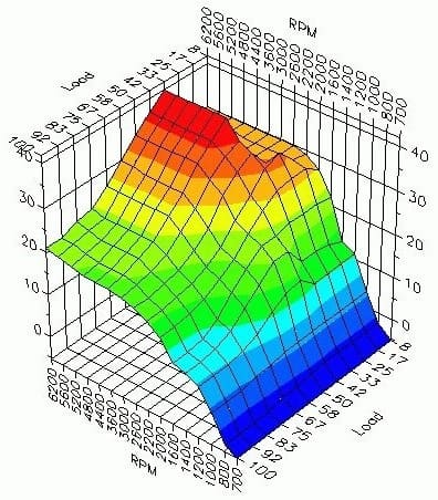
The incoming signals are all processed in a map (see the image above). The map will process the input signals (from the sensors) based on factors such as engine speed, load, outside air, coolant, engine oil, and exhaust gas temperatures. With this data, the map determines what the output will be, such as how an actuator will be controlled. For example, when the engine is cold, more fuel must be injected (cold start enrichment) to keep the engine running. This used to be done manually with the choke, but with engine management, this is all automatically controlled using the VE and AFR tables. These tables represent volumetric efficiency and air-fuel ratios.
The outside temperature and coolant temperature are measured, and when the engine is running, the ignition timing is determined based on the knock sensors, and using RPM sensors, it is determined whether the engine is running smoothly. The throttle will also be controlled to open more. After a certain time has passed, the temperature in the combustion chamber will be high enough to switch to normal injection.
When the engine is in the warm-up phase as just described, this is called “Open Loop.” Feedback from the oxygen sensor is not considered. This sensor measures a much too rich mixture (during cold start enrichment) and would therefore want the engine to run leaner. But because enrichment is necessary, the data from the oxygen sensor is ignored. Once the engine reaches sufficient temperature, the incoming signals from the oxygen sensor are used again. This is then referred to as “Closed Loop.” To summarize: the ECU decides which signals are used or not.
The different maps are described on the page injection system.
Adaptive Memory:
The engine management software includes a so-called “adaptive learning memory.” Here, actuators are controlled based on previously received data from sensors. This accounts for some wear and contamination of the engine. Consider, for example, a lower compression end pressure due to wear, causing idle speed to drop compared to a new engine. The engine management software must adjust by altering the Fuel Trims.
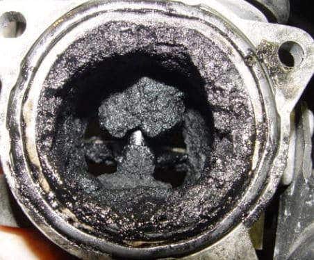
In the adaptive memory, data such as throttle valve opening and closing is stored. Over time, the throttle valve gets contaminated due to EGR influences and crankcase ventilation vapors. The opening and closing of the valve become slightly stiffer, and the valve must open a little more because otherwise, carbon deposits block the airway. The control in a slightly older engine will be different from that in a new engine. Without adaptive memory, the control would need to search for correct values each time the engine is started. With adaptive memory, the engine management software accounts for this.
After cleaning, for instance, the throttle or EGR valve, they often need to be relearned. Relearning resets the adaptive memory. After relearning, the engine management will recheck and store the sensor values. After relearning, the engine might run a bit irregular and shake.
An oxygen sensor slows down as it ages. The data does reach the engine management but the adaptive memory makes the system account for the aging of the sensor. It is thus important to clear the adaptive values after replacing an oxygen sensor.
In the automatic transmission, there are clutches controlled by oil pressure for shifting. Older transmission fluid is often more contaminated and thicker than new oil. Thus, the RPM and shift points will differ with new oil compared to old oil. In the transmission, there’s also a control unit with adaptive memory that has ideally adjusted the shift points over time. After changing the oil, the shifting behavior might change significantly. Consider incorrect RPMs for shifting to higher or lower gears, or abrupt gear engagement causing a jolt in the drivetrain. Therefore, after changing the oil, it’s important to reset the transmission’s adaptive values.
Often, an adaptation drive must be conducted after resetting the adaptive values. The vehicle must then be driven at varying speeds and RPMs to allow the system to calculate and store the correct adaptive values.
The Creation of a Fault Code:
A sensor may be defective. The wiring or connector of the sensor can also become faulty, disrupting the connection between the sensor and ECU. Therefore, the ECU receives incorrect values from the sensor. In the past, this could affect engine operation; a faulty temperature sensor could have caused excessive fuel injection, leading to engine “flooding.” This risk is now significantly reduced. The engine management can recognize when a sensor’s value is incorrect.
In this example, the voltage progression of a temperature sensor is shown. Temperature works with voltages between 0.5 and 4.5 volts. Voltages below 0.5V and above 4.5V fall within the forbidden zone. These voltages can be seen in the graph below. When the sensor is defective or a cable has a short to ground, a voltage of 0 volts is transmitted. This falls within the forbidden zone. The ECU recognizes this and stores a fault code.
Not only is the fault code stored, but the signal is also not used. The ECU switches to a limp mode situation; a substitute value is calculated from other data the ECU receives. The substitute value is close to the real value, so the vehicle can still be driven to the garage. Naturally, ignoring this fault is not advisable, as it could significantly increase fuel consumption.
Adjusting the Software:
The software in the ECU can be adjusted with appropriate equipment and, of course, the knowledge, as improper programming can cause severe engine damage. Reprogramming the software can be done by a manufacturer’s software update (to fix errors discovered afterward) or through tuning. This increases power by adjusting the map in the ECU. More information on this is available on the chiptuning page.