Operation of a PWM-controlled valve:
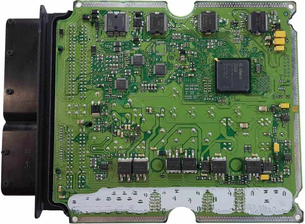
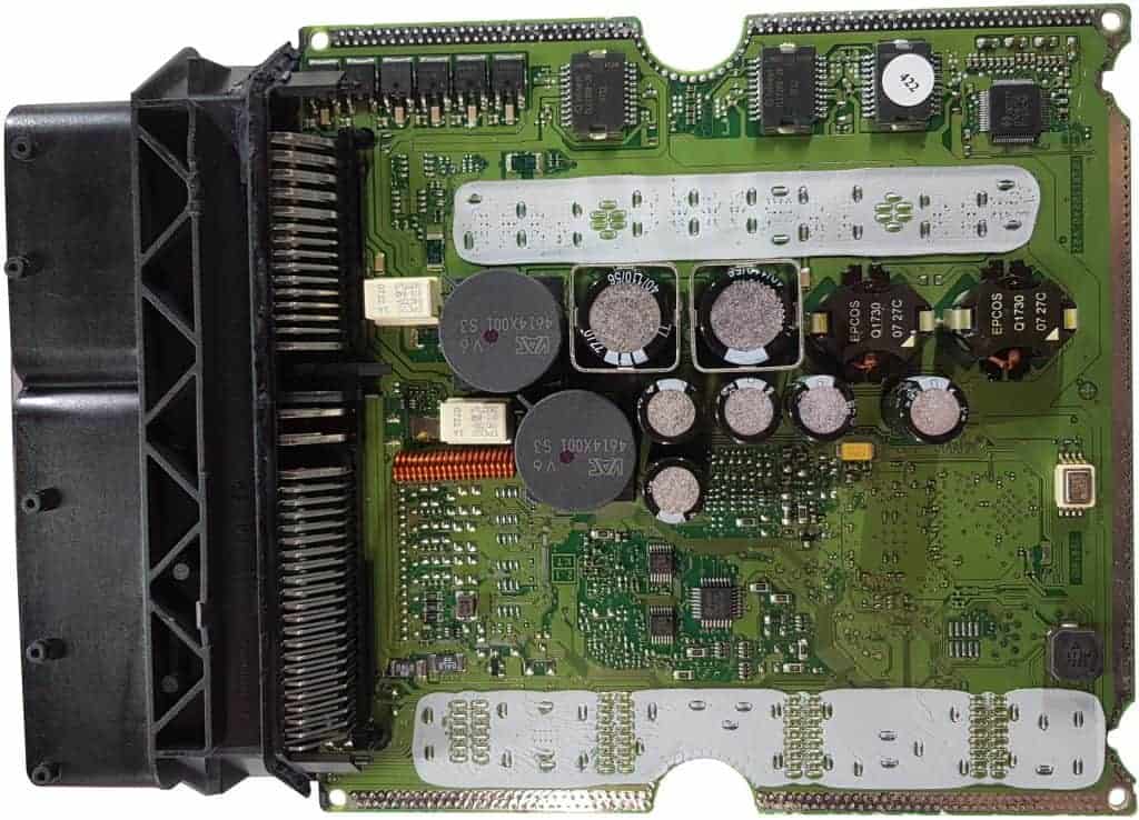
The two images below show the interior of an engine control unit. The covers have been removed. In this section, we provide an example using a diagram and the connections of how a PWM-controlled valve is wired. First, take a look at the top and bottom sides of the circuit board.
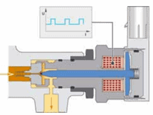
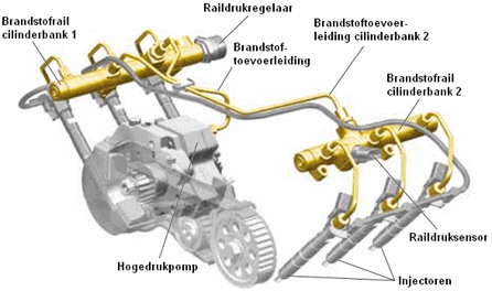
The PWM-controlled pressure regulator is located on the high-pressure line of the common rail. The image below shows the solenoid valve that opens with a PWM signal. Also depicted is an overview of the common rail system.
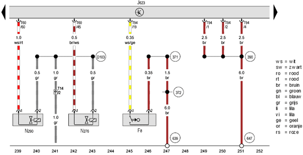
The diagram below is of a 3.0 common rail diesel engine (VAG). We look up the component code of the fuel pressure regulator: the N276.
This fuel metering valve is designed to regulate the fuel pressure in the rail. In this engine, the pressure varies between 300 and 1600 bar, depending on operating conditions.
The N276 receives a supply voltage on pin 2 (gray) that equals the system voltage (between 13 and 14.6 volts with the engine running). Pin 1 is connected with a brown/white wire to pin 45 in the T60 connector on the ECU.0
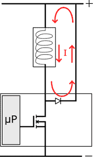
When the ECU switches the valve to ground, a current flows through the coil. The valve is energized and opens. If the ECU interrupts the ground, a spring in the fuel metering valve ensures that it closes again. By doing this very quickly in succession and varying the period that the valve opens and closes, we can describe a PWM control.0
We will examine the circuit of this PWM control using the diagram below and measurements in the connector and on the ECU’s circuit board. How are the components actually wired? How are they visible on the circuit board? And what are the components’ purposes? This section clarifies this.
The image below shows both the interior of the connector and the bottom side of the circuit board. Measurements with the multimeter were used to find the solder connection on the circuit board connected to connector terminal T60/45. These solder points are indicated with the purple arrows.
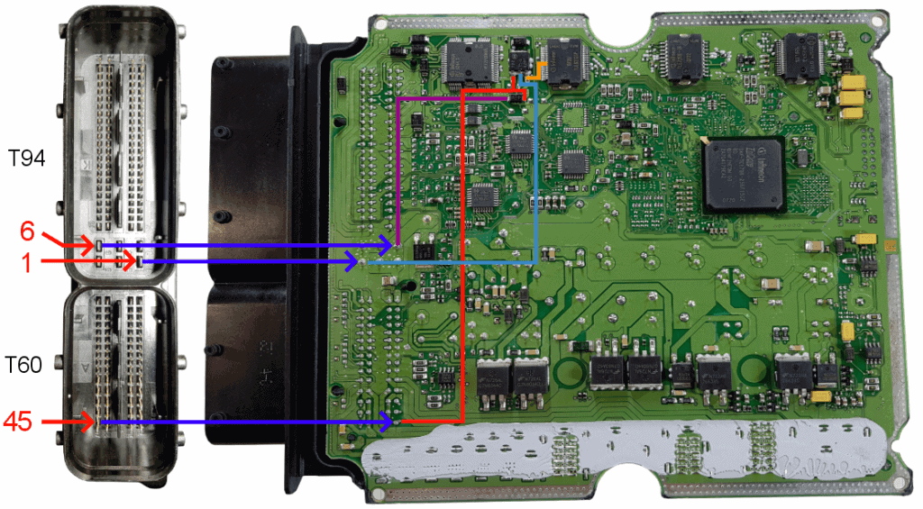
The negative terminal of the fuel metering valve (1) is connected through connector terminal T60/45 to the drain of the FET and the anode of the freewheeling diode. The red lines in the images indicate the solder connections. For clarity, an enlargement of the above image is shown here.
The source is connected to ground through connector terminal T94/1 and is indicated with the blue line.
The microprocessor turns the FET on and off by applying a control voltage to the gate of the FET. The orange line shows the connection between the microprocessor and the gate of the FET.
When the gate receives a control voltage from the microprocessor, the FET conducts, allowing a current to flow from the drain to the source and thus through the coil. The magnetic field energizes the coil, closing the fuel pressure control valve.
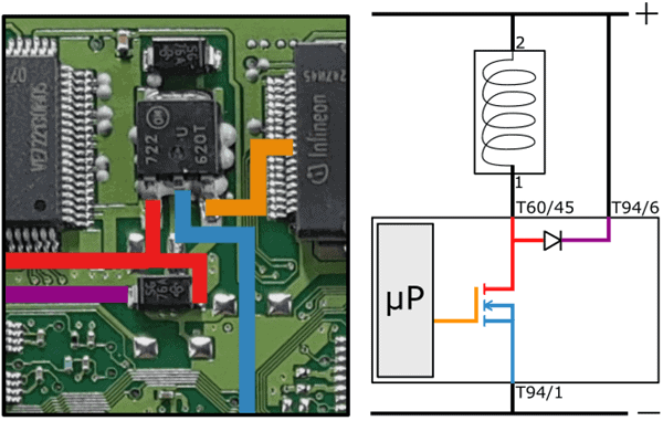
Once the control voltage on the gate is removed, the connection between the drain and source is broken. The freewheeling diode routes the induction current, arising from the residual energy in the coil, to the positive side. This ensures a gradual reduction of current and prevents induction.
The schematic with the fault shows the transition resistance in the positive wire of the coil. The red arrows indicate the current direction with a deactivated FET. Thanks to this circuit, the current can slowly decrease.
Now that we have reviewed the circuits and components of the fuel pressure regulator, we can also examine the oscilloscope images when there is a malfunction. How do we recognize a fault in a PWM signal? What are the effects on the operation of the pressure regulator? You can read this on the duty cycle and PWM control page.