Introduction:
A duty cycle circuit can regulate the current through a consumer. The current can be controlled without power loss, unlike a series resistor. In automotive technology, the duty cycle can be used to regulate the speed of the heater fan, the position of the throttle position motor, or the brightness of lighting.
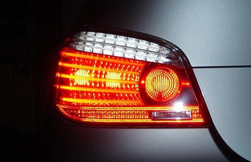
Applying a duty cycle to a lamp can make it glow less brightly. This is used in tail lights, where a single lamp can operate at two different intensities, namely for regular lighting and brake illumination. During normal lighting, the lamp glows dimly (the duty cycle limits the current through the lamp). During braking, the duty cycle changes to make the lamp glow brighter.
The image shows a tail light of a BMW 5-series, where the left lamp also functions as a brake light by glowing brighter.
Measuring a duty cycle:
A duty cycle can be measured with an oscilloscope, which will graphically display the voltage over time.
When measured with a multimeter, the correct voltage value will never be displayed. This is because the voltage varies constantly in a duty cycle, making the multimeter show the average voltage as it’s too slow.

Duty cycle in a positive circuit:
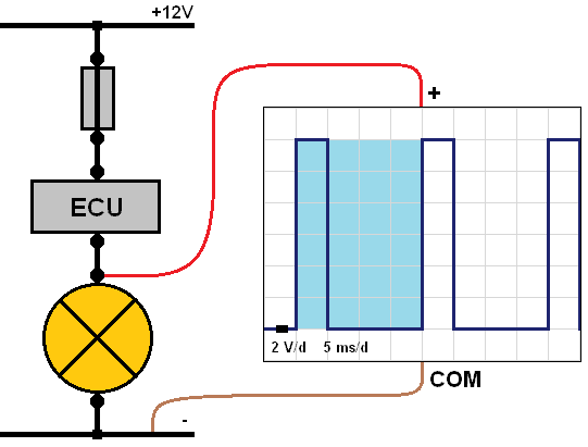
The image below shows a circuit diagram with the battery’s positive terminal (12 volts) at the top, followed by the fuse, ECU (electronic switch), consumer (in this case a lamp), and finally the ground. The ECU continuously switches the supply voltage on and off.
The oscilloscope measures the voltage between the positive terminal of the lamp and the vehicle’s ground. The oscilloscope settings are: 2 volts per division and 5 milliseconds per division. This means each square from bottom to top represents 2 volts, so adding up the squares of the ascending line (a total of 6) gives a maximum measured voltage of 12 volts.
The duration is from left to right. Each square (division) is set to 5 milliseconds. Looking from left to right, it can be seen that the line is high for 10 milliseconds and low for 10 milliseconds.
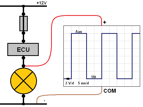
The oscilloscope, like the multimeter, measures the voltage difference between the connected positive and negative cables. If the lamp is on in the diagram below, there is a 12-volt drop on the positive cable and always 0 volts on the negative cable because it’s connected to the ground. The meter displays the difference; between 12 volts and 0 volts, it’s 12 volts. This is shown on the meter’s screen. When the duty cycle is high, the lamp is on. This is not the case with a ground circuit, explained in the next paragraph.
To determine the duty cycle, it’s crucial to know what one period entails. In one period, the voltage is high and then low. After this period, the next one begins. In the oscilloscope image below, one period is marked in blue. Here it is seen that the period lasts 20 milliseconds, namely 10 ms high and 10 ms low. It can thus be read that half the time, the voltage is high, and the other half is low. The duty cycle in this oscilloscope image is 50%. The lamp burns dimly in this case.
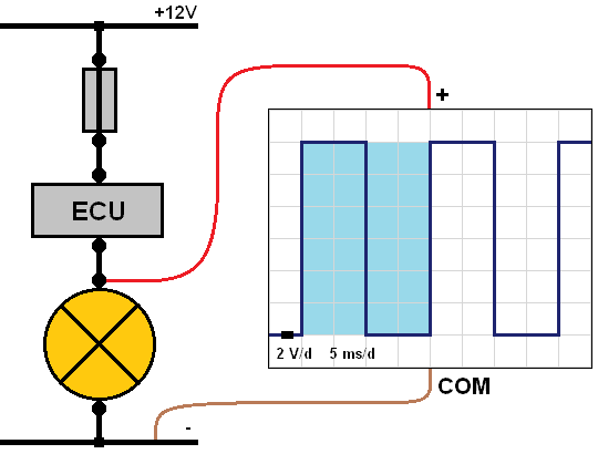
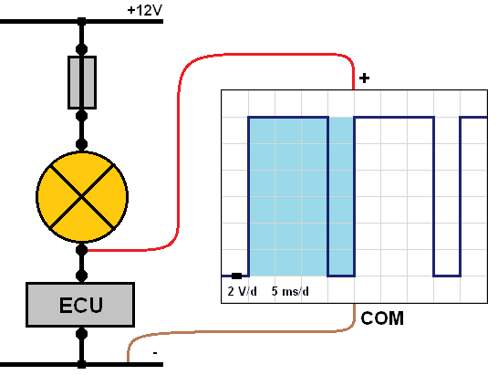
In the image below, the period remains the same (20 ms), but the voltage is high for only a quarter of the time (5 ms) and low for three-quarters of the time (15 ms). In this measurement, the duty cycle is 25%. That means the lamp burns even dimmer than with a 50% duty cycle, as the lamp only receives power for a quarter of the total period.
Duty cycle in a ground circuit:
In automotive technology, ground circuits are commonly used. For a ground-connected consumer, the duty cycle will be the inverse of a positive circuit. An example is seen in the image below.
When the lamp is off, the ECU interrupts the ground connection. This means the circuit is broken. The 12-volt supply is then on the ECU’s input, meaning it’s also on the lamp’s negative terminal. The voltage difference with the lamp off is 12 volts.
As soon as the ECU connects the lamp to the ground, it will turn on. A current flows from positive to negative. The lamp uses 12 volts to light, leaving 0 volts on the lamp’s negative terminal. Both cables have 0 volts. The voltage difference is then 0 volts. This means the lamp is on at 0 volts and off at 12 volts.
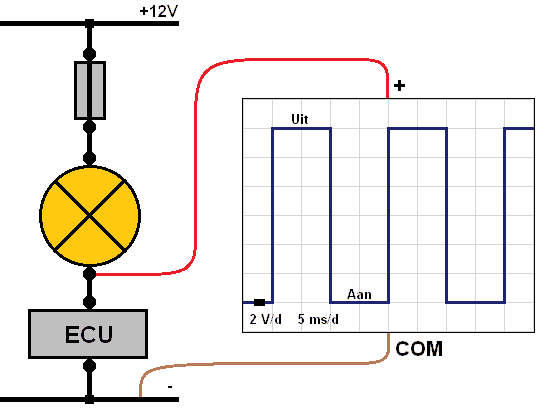
To make the lamp dimmer, the time in which the lamp receives power should be reduced. This is shown in the image below. In one period, the voltage is high for 15 ms (lamp is off) and low for 5 ms (lamp is on). The lamp is now only on for a quarter of the period, causing it to dim.
Duty cycle measured from the power source:
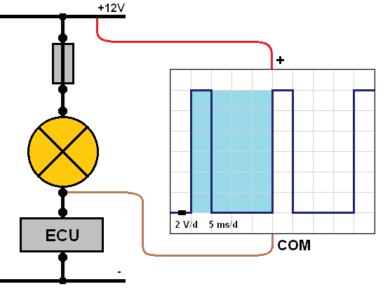
The previous measurements were all made relative to the vehicle’s ground. Another option is measuring from the battery’s positive terminal to the consumer’s ground, as shown in the image below.
When the ECU has connected the ground, the lamp will light up. In this case, the 12-volt supply is used by the lamp to illuminate. A 0-volt signal will appear on the oscilloscope’s negative cable. The positive cable will have a 12-volt supply. Thus, there is a 12-volt difference between the cables, showing 12 volts on the screen indicating the lamp is on. This is 25% of the period.
Once the ECU breaks the ground connection, the 12 volts will also be on the lamp’s negative side. The oscilloscope will show a 0-volt difference when the lamp is off.
Diagnosing a PWM-controlled fuel pressure regulator:
On the page ECU circuit of a PWM valve, the ECU circuit’s setup for a PWM-controlled rail pressure regulator is explained. It’s advisable to first read the information on that page.
The rail pressure regulator on the high-pressure rail of the common-rail diesel engine is controlled by the engine control unit using PWM (Pulse Width Modulation).
When idle, the valve in the pressure regulator opens, allowing the fuel pressure to leave the high-pressure rail via the return. The valve closes when activated, increasing pressure in the rail. When the rail pressure sensor detects a too high pressure, the ECU adjusts the PWM signal.
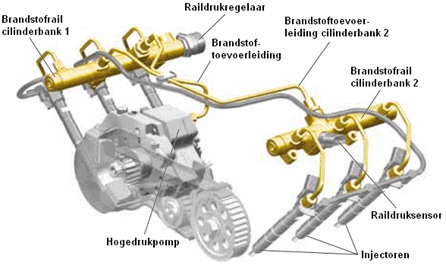
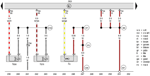
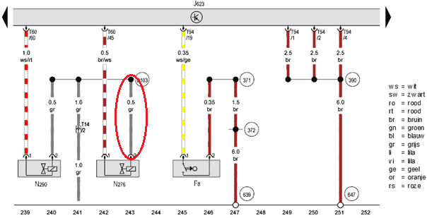
The diagram below shows the engine control unit (J623) and the rail pressure regulator (N276). The rail pressure regulator receives power on pin 2 with a voltage between 13 and 14.6 volts (depending on the charging voltage with the engine running). The ECU grounds pin 45 to activate the valve. Current flows through the N276 coil when pin 45 is grounded, raising the common-rail pressure. When the ECU interrupts the connection between pin 45 and ground, pressure buildup in the fuel rail stops. The spring in the pressure regulator slightly opens the valve again, allowing the fuel to return to the tank via the return lines.
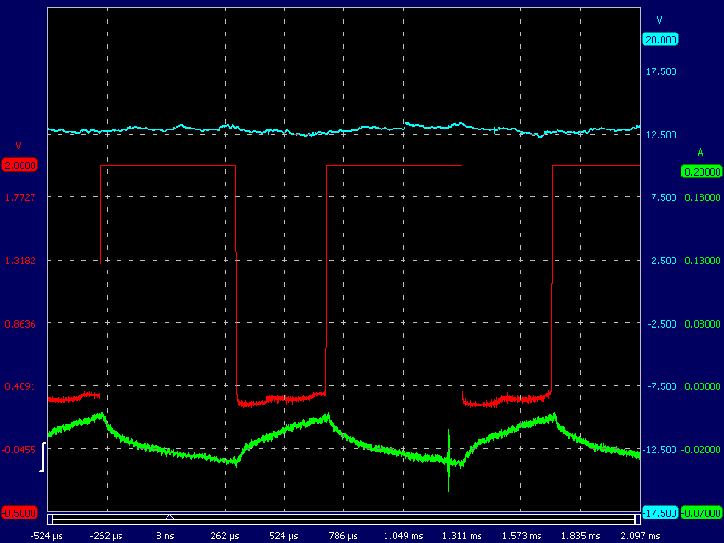
The oscilloscope image shows a supply voltage (blue) and the PWM control (red). The supply voltage is around 13.5 volts and is constant.
The PWM control signal voltage (red) ranges between 0 and 13.5 volts. In this oscilloscope image, the valve is seen to be constantly switching on and off.
The current (green) rises when the valve is energized and decreases when it’s switched off.
In idle mode, the voltage is 13.5 volts. The PWM valve remains unactuated.
A spring inside the valve ensures it’s open when at rest.
When the ECU activates the ground (visible in the oscilloscope image when the red signal is at 0 volts), current flows through the coil (green trace), closing the valve.
The oscilloscope image shows the valve briefly turns on and stays off longer, indicating the fuel pressure should be relatively low.
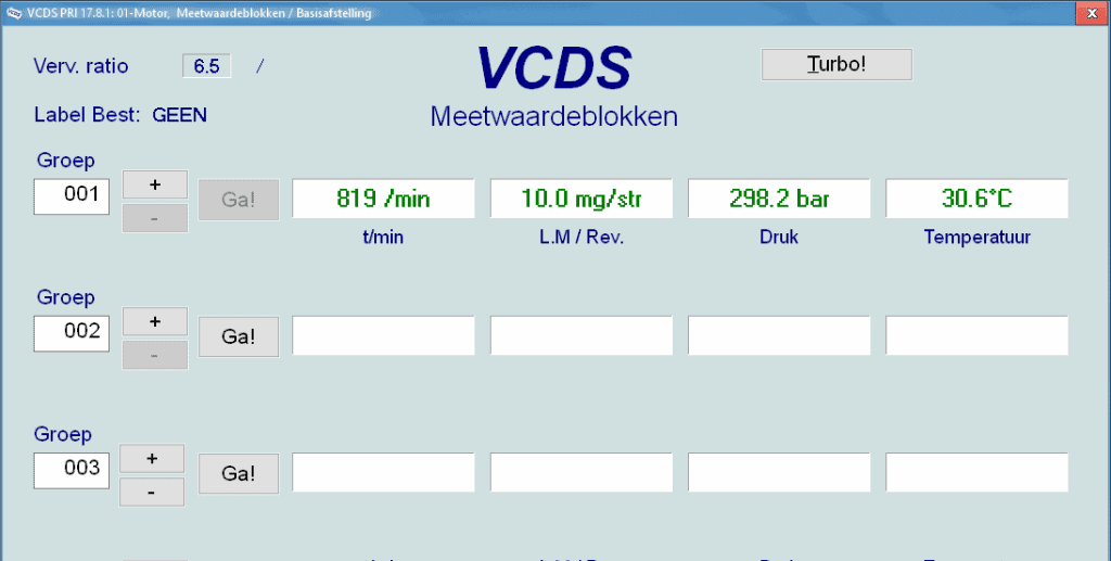
We read the car’s data and check the live data. The fuel pressure is almost 300 bar at idle speed. This is acceptable.
Fault: engine won’t start during cranking.
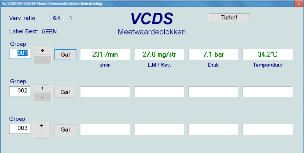
During cranking, the engine won’t start. We are sure there’s enough fuel in the tank. We start by checking for error codes. None are stored. Hence, we check the live data (referred to as measuring value blocks in VCDS). During cranking, the engine speed is 231 rpm. The ECU receives the crankshaft signal. That’s fine.
Fuel pressure during cranking is 7.1 bar. That’s too low for starting.
Low fuel pressure can be attributed to:
- insufficient fuel in the tank
- defective fuel pump (lift pump or high-pressure pump)
- clogged fuel filter
- faulty fuel pressure regulator valve
To determine why fuel pressure remains low, we check the voltages of electrical components with an oscilloscope.
Earlier in this section, the oscilloscope image of a properly working PWM fuel pressure regulator was shown. The next oscilloscope image is another measurement of this pressure regulator, but now with a fault.
As current increases, supply voltage decreases. The supply voltage thus drops when current flows. Additionally, the following points are notable:
- Upon activation, the supply voltage drops to a lower value; normally, a transition resistance causes an abrupt drop (a vertical line in the oscilloscope image to a lower voltage);
- The current buildup follows the coil’s activation, adhering to the exponential loading curve. The current flow during discharge mirrors the gradual buildup of supply voltage. The current doesn’t drop to 0 A, so current continues after deactivating control.
- When the coil is deactivated, there is no inductive peak visible in the red trace (where the voltage rises from 0 to 14 volts). Consider turning off the injector coil where up to 60 volts can emerge.
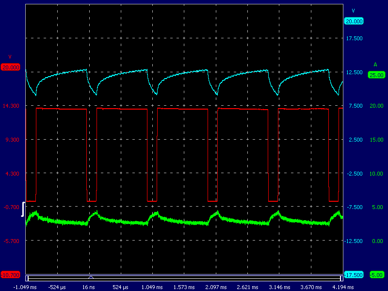
There is thus a transition resistance in the supply wire to the fuel pressure regulator. Only when current flows does voltage loss occur due to the transition resistance. While the ground is disconnected, no current flows, and the supply voltage remains consistent with the battery voltage.
Returning to the diagram: the supply wire is circled in red. The next step is physically locating the damaged wire. Damage may occur from rubbing against engine parts or pinching during earlier assembly work. Once found, the damage can be repaired.
It is now clear what the transition resistance caused. You may have noted the absence of an inductive peak in the oscilloscope signal. When the coil is switched off, the current trace slowly drops to a lower value. Thus, the control is not interrupted; it ends, but current still flows through the coil.
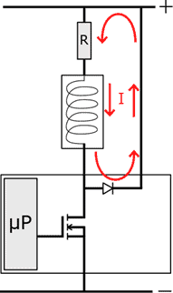
When the FET is made conductive by the microprocessor, current can flow from drain to source and thus through the coil. Consequently, the coil is energized, and the control valve can close against spring force due to the created magnetic field.
Once the FET’s control ends, no current flows through the coil to ground. The freewheeling diode ensures the inductive current from the remaining energy in the coil is redirected to the positive side. This provides gradual current reduction and prevents induction. This process is indicated by the red arrows in the image.
This explains why current flow is still visible in the oscilloscope image after the control has ended.