Degrees of Freedom in Wheel Guidance:
In the suspension system of a car, there are several joints (including those on the control arms and shock absorber) that allow for the degrees of freedom in the overall suspension system. The wheel guidance ensures that the potential degrees of freedom of possible wheel movements are limited to just one or two. If a wheel is not “secured,” it can freely rotate, tilt (in the x and y directions), turn, and move up and down. The wheel is then essentially “detached” from the suspension. It can move in any direction without “guidance.” Each of the aforementioned movements represents one degree of freedom.
The suspension system, hence the wheel guidance, ensures that the freedom of movement is restricted to 1 degree of freedom. This means that the wheel can move freely in only one direction, without input from the driver. That free movement is the up-and-down movement of compressing and releasing the suspension. The wheel can freely move up and down over uneven surfaces.
The suspension of a car is constructed with several linear joints, ball joints, and swivel-slide joints. These joints all influence each other. One joint too many results in too many degrees of freedom (so the wheel can unintentionally move in different directions) or zero degrees of freedom (the wheel cannot move and therefore cannot compress or release).
Joints in Wheel Guidance:
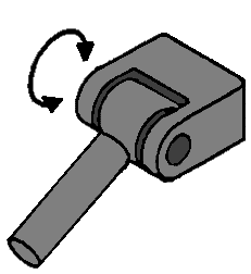
Linear Joint:
This linear joint can move in one direction; up and down. This provides 1 degree of freedom.
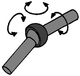
Ball Joint:
With this joint, the respective parts can make three movements relative to each other; a bending, a rolling, and a rotational movement. This joint has 3 degrees of freedom because if the joint is “loose,” it can perform 3 free movements (see arrows).
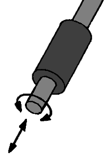
Swivel-Slide Joint:
This joint can perform two movements; a rotational and an in-and-out sliding movement. In principle, this is an example of a shock absorber (from a McPherson strut). These two movements ensure that the swivel-slide joint has 2 degrees of freedom.
Guides in Wheel Guidance:
To form a suspension system out of various types of joints, they sometimes need to be combined into one object, such as a control arm. This control arm is then called a guide. Below are some examples of these guides:
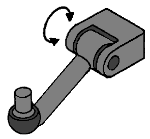
Linear Joint with Ball Joint:
This is a typical example of a control arm, which is connected to the car body (or subframe) on the side of the linear joint and to the steering knuckle on the side of the ball joint. If this entire joint is free, it can move both in the movement direction of the linear joint (1 direction) and the 3 directions of the ball joint. The linear joint has 1 degree of freedom, and the ball joint has 3. Since this part is considered as a single guide, the degrees of freedom can be added together. The 1 and the 3 add up to 4 degrees of freedom.
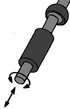
Double Ball Joint:
An example of a guide with a double ball joint is the tie rod with the inner and outer tie rod ends. Each ball joint has 3 degrees of freedom, and since it is one guide, these should be summed up. However, they have the same self-rotation because when one ball joint rotates, the other does too. So 1 degree of freedom from the self-rotation does not count (see the red arrows). The total degrees of freedom for this guide are 6, but in the subsequent calculation, you fill in “self-rotations r” with the number 1. This 1 is then subtracted in the calculation.
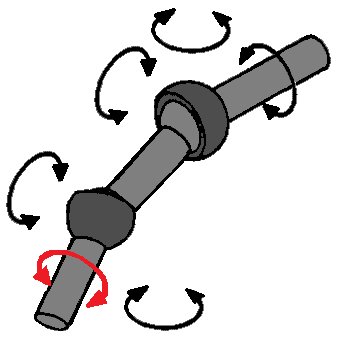
Swivel-Slide Joint with Ball Joint:
As previously mentioned, a shock absorber is a swivel-slide joint. However, every McPherson strut also has a ball joint at the top, although you might not initially think so. At the top of the shock absorber is a rubber. This rubber provides some movement freedom for the shock absorber and has the properties of a ball joint. Thus, a shock absorber has both the 2 degrees of freedom of the swivel-slide joint and the 3 degrees of freedom of the ball joint, making a total of 5. Again, there is self-rotation as the rotational movement of the swivel-slide joint is the same as the rotational movement of the ball joint. So, for the “r” of self-rotation, 1 should be added.
Calculating Degrees of Freedom:
Based on the data of the suspension system, the number of degrees of freedom can be calculated. To fill in the formula correctly, the joints and guides must be categorized:
- L for the number of guides
- g for the number of joints and hinges
- r for the number of self-rotations (as with the double ball joint in one guide)
In addition, the following letters are used:
- k for the number of wheel carriers (in most cases 1, as this is the steering knuckle)
- b5fi for the total number of degrees of freedom for all joints and hinges combined.
F = 6 (k + L – g) -r + b5fi
Example:
In a suspension system, there are: k 1 wheel carrier (steering knuckle), L 2 guides, g 5 joints, r 2 self-rotations, b5fi 15 total degrees of freedom
In formula form, this is:
F = 6 (1 + 2 – 5) – 2 + 15
F = 6 x (-2) – 2 + 15
F = 1
There is now 1 degree of freedom, so this is correct. The wheel can make a pure up-and-down motion.
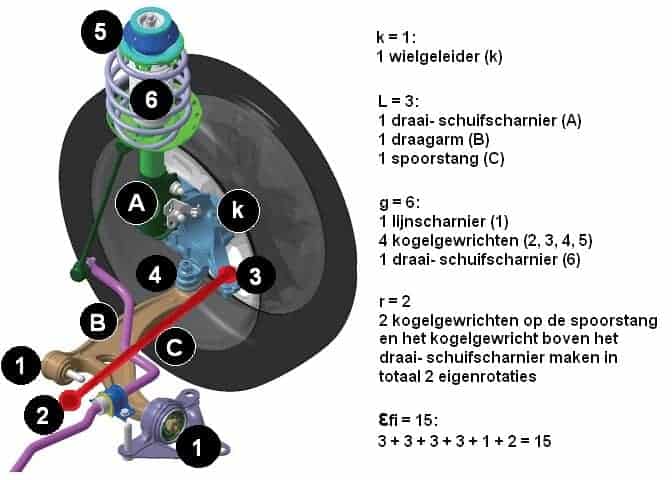
To clarify, here is an example with an illustration of a suspension system:
The image below is of a McPherson strut with the corresponding legend. The letters A, B, and C represent the guides, and the numbers 1 to 6 represent the joints / hinges.
b5fi are the degrees of freedom of the joints summed up; hence 3 degrees of freedom per ball joint (thus 4 x 3), 1 degree of freedom for the linear joint, and 2 degrees of freedom for the swivel-slide joint.
The formula can be filled out as follows:
F = 6 (k + L – g) -r + b5fi
F = 6 (1 + 3 – 6) – 2 + 15
F = 6 x (-2) – 2 + 15
F = -12 – 2 + 15
F = -14 + 15
F = 1 degree of freedom