Subjects:
- Degrees of freedom in the wheel guide
- Hinges in the wheel guide
- Guides in the wheel guide
- Calculate degrees of freedom
Degrees of freedom in the wheel guide:
The wheel suspension of a car contains a number of hinges (eg on the wishbones and shock absorber) that provide the degrees of freedom in the total wheel suspension. The wheel guide ensures that the possible degrees of freedom of the possible wheel movements are limited to just one or two. If a wheel is not “held” firmly, it will be able to freely rotate, tilt (in x and y direction), spin, move up and down. The wheel is then in principle “loose” from the suspension. It can move in any direction without “guidance”. Each movement just mentioned is one degree of freedom.
The wheel suspension, i.e. the wheel guide, ensures that the freedom of movement is limited to 1 degree of freedom. This means that the wheel can move “freely” in only 1 direction, without the influence of the driver. That free movement is the up-and-down movement of the springing in and out. The wheel can bounce in and out unhindered over an uneven road surface.
The wheel suspension of a car is constructed with a number of line hinges, ball hinges and rotary-slide hinges. These hinges all influence each other. A hinge too much results in too many degrees of freedom (so the wheel can move in different directions unintentionally) or for 0 degrees of freedom (the wheel can't move and therefore cannot bounce in and out).
Hinges in the wheel guide:
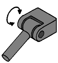
Line Hinge:
This line hinge can move in 1 direction; up and down. This provides 1 degree of freedom.
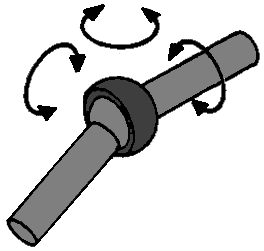
Ball joint:
With this hinge, the relevant parts can make 3 movements relative to each other; a nodding, rolling and turning movement. This hinge has 3 degrees of freedom, because when the hinge is “loose”, it can make 3 free movements (see arrows).
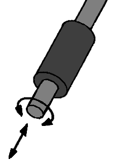
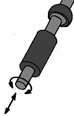
Turn-slide hinge:
This hinge can make 2 movements; a rotating and a retracting and extending movement. Basically this is an example of a shock absorber (from a McPherson strut). These 2 movements ensure that the rotary-slide hinge has 2 degrees of freedom.
Guides in the wheel guide:
In order to make a wheel suspension from various types of hinges, hinges sometimes have to be combined on 1 object, eg a wishbone. We call this support arm a guide. Below are a few examples of these conductors:
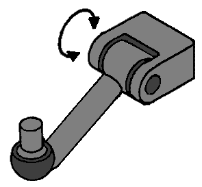
Linear hinge with ball joint:
This is a typical example of a wishbone, which is connected to the body (or subframe) on the side of the line hinge and is connected to the steering knuckle on the side of the ball joint. When this whole hinge is loose, it can move in both the direction of movement of the line hinge (1 direction) and the 3 directions of the ball joint. After all, the line hinge has 1 degree of freedom and the ball joint has 3. Because this part is seen as 1 conductor, the degrees of freedom can be added together. The 1 and the 3 then make it 4 degrees of freedom.
Double ball joint:
An example of a double ball joint guide is the tie rod with inner and outer tie rod balls. Each ball joint has 3 degrees of freedom, so since it is 1 conductor, these should be added together. However, they have the same self-rotation, because if 1 ball joint makes a rotating movement, the other will also. So 1 degree of freedom of the self-rotation does not count (see the red arrows). The degrees of freedom for this conductor are a total of 6, but in the calculation that follows, you enter the number 1 at “eigenrotations r”. This 1 is then subtracted from the calculation.
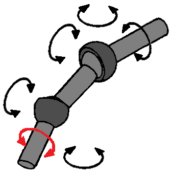
Swivel-slide hinge with ball joint:
As mentioned before, a shock absorber is a twist-slide hinge. However, with every McPherson strut there is also a ball joint above it, even if you would not think so at first. At the top of the shock absorber is another rubber. This rubber provides some freedom of movement for the shock absorber and therefore also has the properties of a ball joint. A shock absorber therefore has both the 2 degrees of freedom of the rotary-slide hinge and the 3 degrees of freedom of the ball joint, which together makes 5. Again, there is a self-rotation, because the rotational movement of the rotary-slide hinge is the same as the rotational movement of the ball joint. So to the “r” of self-rotation 1 will have to be added.
Calculating degrees of freedom:
The number of degrees of freedom can be calculated on the basis of the data from the wheel suspension. In order to properly fill in the formula of this, the hinges and guides must be divided into categories:
- L for the number of conductors
- g for the number of joints and hinges
- r for the number of self-rotations (as with the double ball joint in 1 guide)
In addition, the letters are added:
- k for the number of wheel carriers (in most cases 1, because this is the knuckle)
- εfi for the degrees of freedom for the total number of joints and hinges added together.
F = 6 (k + L – g) -r + εfi
Example:
In a wheel suspension are: k 1 wheel carrier (knuckle), L 2 guides, g 5 joints, r 2 self-rotations, εfi 15 total degrees of freedom
In formula form this is:
F = 6 (1 + 2 – 5) – 2 + 15
F = 6 x (-2) – 2 + 15
F = 1
So there is now 1 degree of freedom, so this is good. The wheel can make a pure up and down movement.
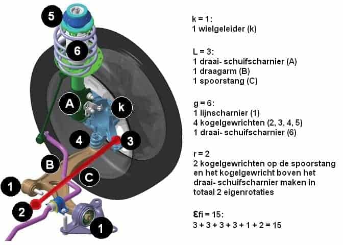
To clarify this, here is an example with an image of a wheel suspension:
The image below is of a McPherson strut with the accompanying legend. The letters A, B and C stand for the guides and the numbers 1 to 6 stand for the hinges / joints.
εfi are the degrees of freedom of the hinges added together; so 3 degrees of freedom per ball joint (so 4 x 3), 1 degree of freedom of the linear hinge and 2 degrees of freedom of the rotary-slide hinge.
The formula can be filled in with this:
F = 6 (k + L – g) -r + εfi
F = 6 (1 + 3 – 6) – 2 + 15
F = 6 x (-2) – 2 + 15
F = -12 – 2 + 15
F = -14 + 15
F = 1 degree of freedom