Topics:
Introduction:
In a car, we find many types of cooling fans: in the engine bay, in a multifunction radio, in battery packs of hybrid and electric vehicles, see: alternative drive. This page focuses on the engine cooling fan.
The cooling fan of a car with an internal combustion engine protects the cooling system from overheating. The cooling fan comes in various designs (see the different sections on this page) but they all have one common feature: the plastic fan blades are located in the front end, near the radiator (sometimes at the front, usually at the back). The fan starts spinning when the coolant has warmed up, or when the air conditioning is turned on.
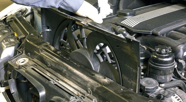
In the above image, we see an electric cooling fan of a BMW in a plastic housing. The cooling fan is removed by a mechanic from the engine bay by sliding it up out of its guides.
The following sections discuss the different methods of controlling the cooling fan.
Fan with Viscous Coupling:
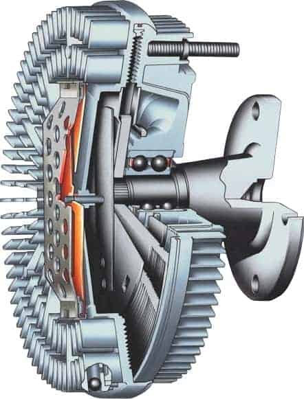
In addition to the electronically controlled fan, there is also a self-regulating fan, namely the version with a viscous coupling. No electronics are involved here. A bimetal strip and liquid silicone fluid are responsible for turning the fan on and off through temperature changes by coupling two chambers (the reservoir chamber and the working chamber) together.
The viscous coupling is attached to the coolant pump flange. In the image, we see part of the flange. The viscous coupling in question is bolted to the coolant pump with four bolts. There are also versions with a single central fastening nut.
The viscous coupling is located behind the radiator. The air flowing through the radiator heats the viscous coupling. A bimetal strip heats up as well and bends as a result. When bending, the bimetal strip opens a leaf spring valve, allowing the silicone fluid to flow from the reservoir chamber to the working chamber. The fluid enables the rotation of the drive plate (engine side) to be transferred to the fan housing (fan side). The silicone fluid can flow back to the reservoir chamber via the return channel.
- When the engine is cold, the fan is off. The flange on the coolant pump rotates, but the fan housing remains stationary. In this situation, no chambers in the viscous coupling are connected;
- When the engine is warm, the fan turns on. The silicone fluid in the working chamber ensures that the fan housing is engaged and starts rotating.
The degree to which the bimetal strip bends (which depends on the air temperature) determines how much fluid can flow into the working chamber. More fluid in the working chamber results in less slip and thus a higher fan speed. There is always a minimal slip present in the viscous coupling.
While driving, the airflow cools the viscous coupling. Therefore, the cooling fan will primarily operate when standing still or driving slowly.
We can recognize by the sound whether a car has a cooling fan driven by an electric motor or a viscous coupling. The viscous coupling is driven by the crankshaft via the serpentine belt. A higher crankshaft speed results in a higher fan speed. If the fan blows harder as the engine speed increases and shuts off after a few seconds due to cooling, the car is equipped with a viscous coupling. An electric fan will not change its speed at idle or during acceleration.
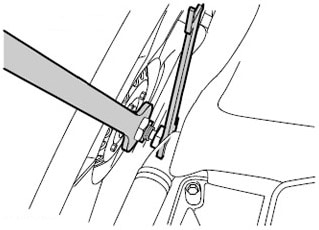
The following image shows the disassembly process of the viscous coupling with a central nut connection. With two large open-end wrenches, the nut connection, and thus the viscous coupling including the fan, can be removed. By moving the wrenches in opposite directions, the coupling can be detached from the coolant pump. The disassembly possibility depends on the car type. Not in all cases can the fan be unscrewed with two wrenches:
- only one nut is on the viscous coupling, and a blocking possibility is absent. By placing a wrench on the nut and giving it a blow with a hammer, the nut comes off the coolant pump slightly. Note: this can damage the bearings and seal of the coolant pump!
- the fan can be blocked with special tools with some notches.
Electrical Fan Control via a Thermoswitch:
In this system, the electric cooling fan is turned on and off with a temperature-dependent switch, i.e., the thermoswitch. This component is located in the radiator.
The thermoswitch is positioned above the hose which acts as a return hose; the coolant cooled in the radiator returns to the engine through this hose. During driving, the airflow primarily ensures sufficient cooling. When the coolant on the outlet side of the radiator becomes too hot, the contacts in the thermoswitch close. This creates an electrical connection on the control current side of the relay circuit, and the fan relay is activated. The fan is powered and starts rotating.
During fan operation, the coolant in the radiator cools down again. Once the temperature is low enough, the thermoswitch breaks the electrical connection. The relay, and thus the fan, turn off.

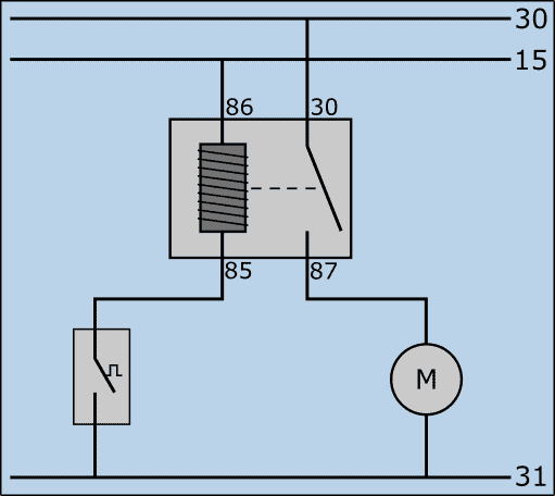
The following electrical diagram shows the control method of the cooling fan. In the diagram, we see:
- that it is a waterfall diagram, with terminal 30 (battery plus) at the top, terminal 15 (ignition switch output) below it, and terminal 31 (battery ground) at the bottom;
- the relay with terminals 86 and 85 (in and out control current) on the left side and terminals 30 and 87 (in and out main current) on the right side;
- the thermoswitch between terminal 85 and the battery ground;
- the cooling fan between 87 and the battery ground.
The thermoswitch operates the control current side of the fan relay. When the temperature in the radiator threatens to become too high, the switch closes. The control current circuit of the relay is closed; current flows through the coil between terminals 86 and 85. The coil becomes magnetic and closes the switch between terminals 30 and 87. As a result, a main current flows from the battery plus through the electric motor to the ground. The fan operates until the relay contact is opened.
Electrical Fan Control via a Control Unit:
Nowadays, we increasingly see cooling fans controlled by a control unit. With this design, there is no need for a thermoswitch: the control unit reads values from one or more coolant temperature sensors and determines the fan control based on that. Advantages of ECU control are:
- Control (on and off moments) can be regulated much more precisely than with the thermoswitch design;
- One cooling fan can take over the function of what used to be two separate (often one large and one small) fans.
The control unit decides when the fan turns on or off and at what speed it operates. The current to the fan does not go through the control unit: the current strength is so high that excessive heat would develop in the control unit. ECU-controlled fan systems can be implemented in two ways:
- Relay Control;
- PWM Control.
These two systems are described in the following sections.
Electronic Fan Control via a Control Unit (Relay Control):
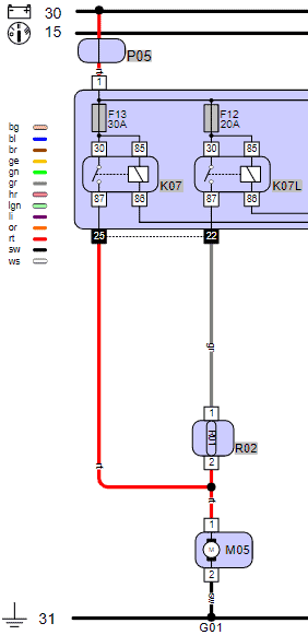
As described in the previous section, ECU control replaces the system with the thermoswitch. The following diagram shows the circuit of a cooling fan control of a Fiat Grande Punto 199. a0In this diagram, we see the following main components:
- R02: fan resistor;
- M05: radiator fan;
- K07: high-speed relay;
- K07L: low-speed relay;
The engine control unit determines based on the coolant temperature and the value of the high-pressure sensor in the air conditioning system, whether and at what speed the cooling fan should operate. When the air conditioning is turned on, speed 1 is automatically activated, and speed 2 is activated when the engine is (too) warm. 0a0The fan (M05) can be controlled at two speeds:
- For low speed, the engine ECU grounds the coil of relay K07L. The relay switches on the main current, which reaches the electric motor of the fan via the series-connected resistor R02.
- For high speed, the ECU switches off relay K07L and activates K07: the electric motor is now powered without the resistor. The fan operates at maximum speed. This occurs, for example, when the engine is very warm in a traffic jam or during a temperature circuit error: for safety, the ECU drives the cooling fan at the highest possible speed.
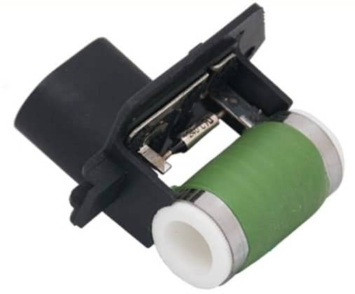
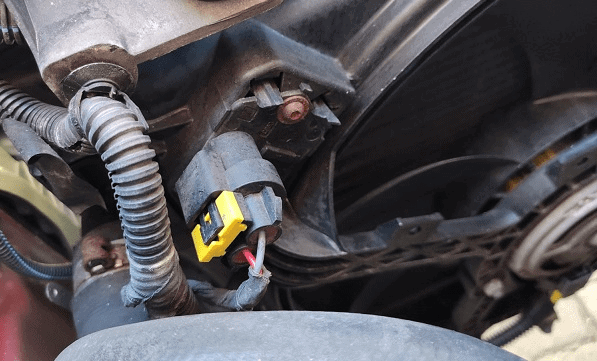
The two images below show the resistor R02 (left) and the location of the resistor in the fan housing (right). The white and green plastic part on the resistor is hollow inside: the cooling fan blows air through it. The metal strips dissipate the heat of the resistor to the flowing air. This element prevents the resistor from overheating.
The advantage of the relay circuit and pre-resistor is that it is a relatively simple system. In case of a malfunction, the voltages from and to the relay can be easily measured. See the troubleshooting method on the relay page.
The disadvantage is the use of the pre-resistor in position 1. A resistor absorbs energy, resulting in energy loss. In addition, the resistor is susceptible to defects. If the resistor burns out, the fan no longer works at position 1. If you suspect the pre-resistor is defective, the resistance can be measured. Disconnect the plug and measure the resistance on the component pins. An outcome of “OL” or “1.” indicates an infinite resistance, indicating a defect. A resistance of a few ohms is normal.
When a car has a single fan relay and the fan starts at high speed, it affects comfort. The sound of the fan switching on and off can be disturbing. Additionally, there will be a peak in energy demand when it starts: consumers such as the lighting may briefly dim after switching on the relay and starting the fan.
Electronic Fan Control via a Control Unit (PWM Control):
The PWM-controlled cooling fan allows the fan speed to be continuously increased or decreased. With a thermoswitch, the fan operates at maximum speed after activation, or with a pre-resistor, it can operate at low or high speed. However, with PWM control, the cooling fan can run at any desired speed. Advantages over the fixed-speed system include:
- More comfort: the fan is much quieter when running at the lowest possible speed than when operating at a (too) high speed with an on-off control. Additionally, the constant or low speed will not affect the lighting, which dims momentarily in the previously discussed system;
- Energy Saving: if little cooling is needed, the fan does not need to run at full speed, saving energy (and thus fuel);
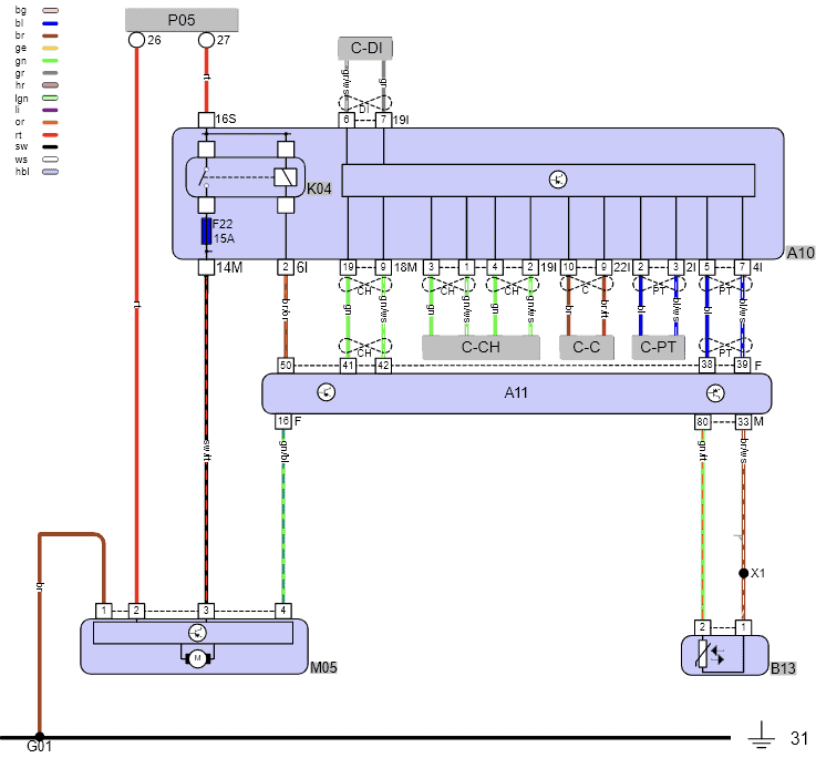
The following diagram is from the cooling system of a Mercedes C-180. In this diagram, we see, among other components:
- P05: main fuse box;
- K04: main relay;
- A10: engine bay electronics module;
- A11: engine ECU;
- M05: radiator fan;
- B13: coolant temperature sensor.
In this diagram, we see that the cooling fan receives a constant plus at pin 2 through the fuse box, a switched plus at pin 3 when relay K04 is engaged by the ECU, and a control signal at pin 4 from the engine ECU.
The engine ECU controls the cooling fan with a PWM signal. The control depends, among other things, on the engine temperature.
For cooling fan faults, we can check if the motor receives a constant and switched plus (pins 2 and 3) relative to the ground (pin 1). If these voltages are correct (at least 12 volts with the engine running), we measure whether the control signal (PWM) from pin 16 on the ECU reaches pin 4 of the fan.
An ECU is also housed within the casing of the cooling fan M05: this is the fan control unit. The engine ECU constantly sends a control signal to the fan ECU; even when it should not be operating. This way, the fan ECU recognizes that communication is good and that the fan should remain off. When this signal is missing or incorrect, the ECU can no longer determine if the fan should stay off or at what speed it should operate. For safety reasons, the ECU drives the cooling fan motor at full speed. The car’s driver will notice that when he/she turns on the ignition, the fan will blow very hard.
It can happen that the fan keeps spinning hard with the ignition on or off (strongly depending on the car type). If the control signal from the engine ECU is correct, the fan ECU may be faulty.
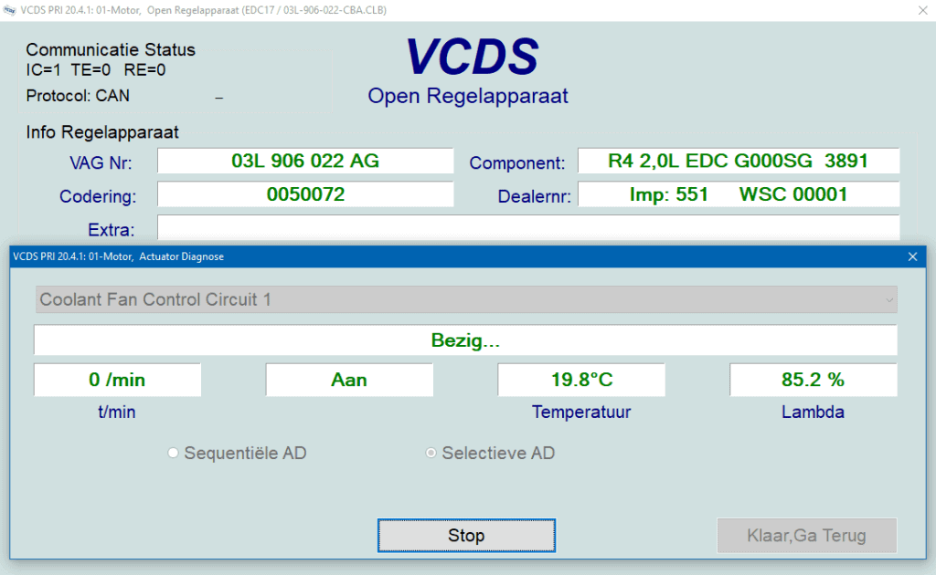
Another possible fault might be that you suspect the fan does not spin at all. To drive the fan during diagnosis, we can control it with diagnostic equipment via the actuator test while measuring the power supply and control voltages at the same time.
The next screen shows the actuator test of the cooling fan (Coolant Fan Control Circuit 1) in the VCDS program. a0
After clicking “Start,” the VCDS program sends a command to the engine ECU to control the cooling fan. The control then takes place: every five seconds, the fan runs at maximum speed and then turns off again.
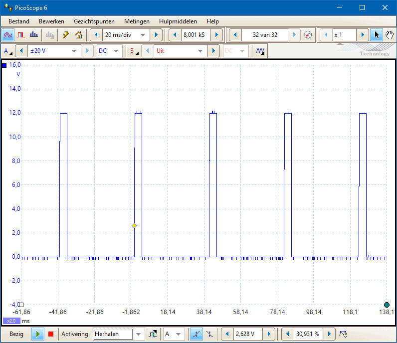
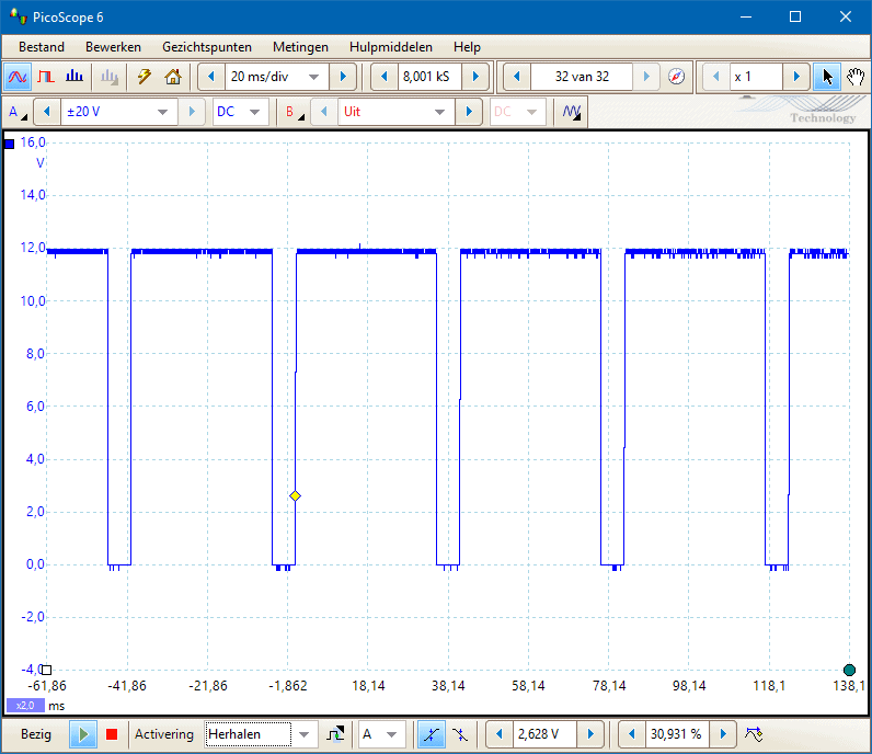
The scope images below show the PWM control signals with the fan off (left) and at full speed (right).
The fan can run at any desired speed by lengthening or shortening the active part of the signal.
Possible Faults Causing the Cooling Fan to Keep Running:
It can occur that a cooling fan runs at high speed, even when the engine is off. Here is a list of the most common faults causing the cooling fan to enter a so-called “limp home mode.”
- One or more error codes: read the error codes from the engine management or air conditioning system. There may be an error code concerning the coolant temperature sensor, high-pressure sensor, or their wiring;
- The coolant temperature sensor shows an illogical value. Check the actual temperature using live data during diagnostics;
- The radiator is clogged. This can be a coolant channel, preventing proper coolant circulation, or a blockage in the air passage. The latter is easy to check: visually inspect the radiator for visible damage.
- The relay is sticking: this is primarily applicable to the version with a pre-resistor;
- There is poor communication between the engine ECU and the fan ECU: this applies to the PWM-controlled fan ECU. Signals on both ECUs can be measured with an oscilloscope. There should be no difference. If there is a voltage difference, you may be dealing with a broken wire, a transition resistance, or a short circuit.