Compression end pressure:
During the compression stroke, the intake and exhaust valves are closed, and the piston moves upward. The air present (or the air/fuel mixture) is thereby compressed. Once the piston reaches TDC (top dead center), the maximum compression pressure is achieved. This is referred to as the compression end pressure. Once fuel is supplied to the present air, the spark plug will spark to ignite the mixture. Due to combustion, the piston is pushed down, and the crankshaft rotates.
The compression end pressure depends, among other things, on the compression ratio.

Measuring compression:
If the compression end pressure is too low, the maximum achievable energy from the fuel cannot be harnessed. This results, among other things, in power loss. If the compression end pressure of only one cylinder is too low, the engine will shake and vibrate, and in most cases, a cylinder misfire error will be stored.
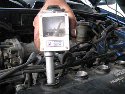
By measuring the compression, the engine’s compression end pressure can be assessed. A self-recording compression gauge records the pressure built up in the cylinder. The technician determines, based on this pressure, whether the compression end pressure is acceptable.
Step-by-step guide to measuring compression:
1. Ensure the engine is at operating temperature. The engine components have expanded due to the heat, so the values measured are realistic.
2. Remove the spark plugs.
3. If possible, disconnect the fuel supply by removing the connectors from the injectors. The injectors will not be triggered during starting, so no unburnt fuel enters the engine.
4. Insert the compression gauge into the spark plug hole. The rubber end of the compression gauge provides the seal between the gauge and the cylinder head.
5. Have someone else start the engine and keep the accelerator pedal fully depressed. The throttle valve opens fully, ensuring the drawn-in air is not restricted.
6. Press the compression gauge firmly against the cylinder head while starting the engine. Hissing sounds indicate air is leaking past the compression gauge. The value on the compression gauge will remain too low.
7. Once the needle on the compression gauge stops moving further to the right, stop starting. Often 3 to 5 seconds of starting is sufficient for a good measurement.
Repeat steps 4 through 7 for each cylinder. When measuring another cylinder, ensure the measurement is taken on a different part of the card. Click the button on the compression gauge. The card slides upward. Below are some situations that occur in practice:
The compression end pressure of all four cylinders is high enough, and none of the cylinders deviate. The measurement indicates that the engine’s compression end pressure is good.
In cylinder 3, the pressure is lower than in the other cylinders. Insufficient pressure is built up in cylinder 3. This indicates a problem. This could be an issue with the sealing of one or more valves, or a problem with the piston rings.
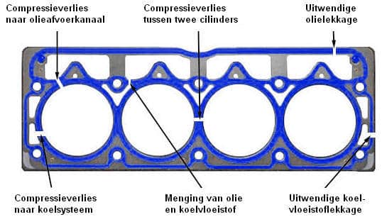
A deviation between two adjacent cylinders likely indicates a crack in the gasket or the cylinder head between the two cylinders. During the compression stroke of cylinder 2, air leaks to cylinder 3, and vice versa.
If the compression end pressure of all cylinders is too low, several causes may be present. These can include worn or stuck piston rings.
With the compression measurement, it can be determined that the compression end pressure is not in order. It is not possible with this method to determine what causes it. Possible ways to make a further diagnosis include:
- Pouring a little engine oil into the spark plug hole (not too much!). With worn compression rings, the oil will temporarily provide better sealing. A second measurement will therefore be better, or even acceptable.
- Disassembling engine components for a visual inspection.
- Conducting a cylinder leak test.
A modern method of measuring compression is analyzing an oscilloscope trace with a in cylinder pressure measurement. Unlike the (classical) compression measurement discussed in this section, not only is the compression end pressure measured, but also the pressure during the intake, power, and exhaust strokes. This can be done both during starting and operating of the engine under various conditions. Since the measurement method, analysis of the trace, and evaluation of the signals are extensive, the cylinder pressure measurement is described on a separate page.
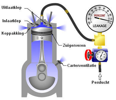
Cylinder leak test:
A cylinder leak test can identify the cause of compression loss. A cylinder leak test uses compressed air to pressurize the cylinder space. A manometer connected to the leak tester indicates the leakage in percentage. If leakage is present, the manometer will display a value greater than 0%. If the air pressure in the combustion chamber remains constant, the meter shows 0%. Note that during this test, the valves should be closed; conduct the test with the piston at TDC and during the compression stroke. When the piston is nearly at the top but during the exhaust or intake stroke, the valve often stays slightly open due to valve overlap. Leakage along the valve will then occur, but this is a characteristic, not a defect. If necessary, remove the valve cover to ensure the cams of the camshaft are facing upward.
Step-by-step guide for the cylinder leak test:
- Ensure the engine is at operating temperature. The engine components have expanded due to the heat, so the values measured are realistic.
- Place the piston of the cylinder being measured at TDC. Ensure the engine is in the compression stroke, so the valves are closed.
- Engage the handbrake and put the car in gear. This prevents the air pressure from pushing the piston down. The car should not be on a lift.
- Apply compressed air to the cylinder.
- Read the meter.
If the meter reads 0%, no leakage is present. Connect the leak tester to the next cylinder. If the meter shows a value, leakage is present. Since there is compressed air on the cylinder, the air escapes somewhere. Some possibilities are:
- Blowing sound in the intake pipe of the air filter: intake valve leaks
- Blowing sound in the exhaust: exhaust valve leaks.
- Blowing sound after removing the oil filler cap: air leakage to the oil pan; this can be due to a defective gasket or worn piston rings.
- Blowing sound at cylinder 3 while there is air pressure on cylinder 2; the gasket between cylinder 2 and 3 is cracked.
- Air bubbles in the cooling system: gasket or cylinder head cracked.
Relative compression test with the oscilloscope:
The compression test can also be graphically represented with the oscilloscope. There is no need to disassemble engine parts (such as spark plugs). The compression measurement is carried out by measuring the current of the starter motor. The test is performed during engine starting, so ensure the engine does not start. Disconnecting the connectors from the injectors will prevent fuel injection, so the engine will not start. Make sure to not only disable the ignition! If only the ignition coils of a petrol engine are disconnected, the engine will continue to inject fuel, and the fuel will end up directly in the exhaust.
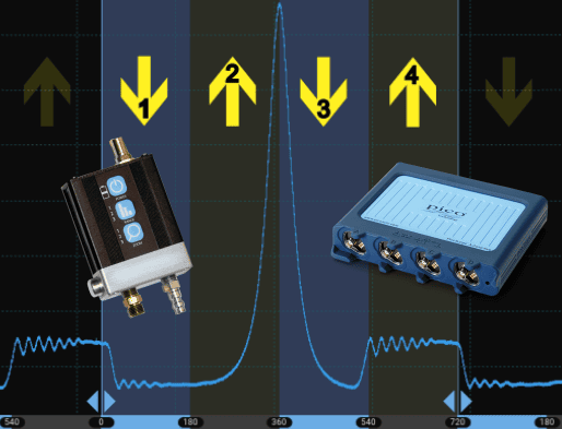
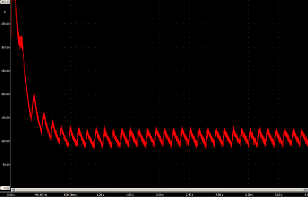
This oscilloscope trace is from a relative compression test performed on a three-cylinder engine.
The current is shown relative to time. The measurement is carried out by connecting the current probe to the ground cable from the chassis to the battery and measuring the current that arises during starting. Each compression stroke causes the starter motor to “struggle” more to turn over. During the compression stroke, the starter motor will need more current to turn. This is visible in the peaks of the oscilloscope trace. If no deviation is observed in the peaks, the result of the relative compression test is satisfactory.
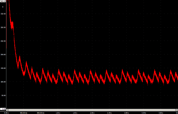
The displayed oscilloscope trace is of a three-cylinder engine where one cylinder has no compression. Compared to the trace above, it can be seen that one peak is missing. The trace indicates compression loss. There is one high peak (cylinder 3), one low peak (cylinder 2), and a peak in between (cylinder 1). The lowest peak (from cylinder 2) indicates that this cylinder has too low compression end pressure. During that compression stroke, the starter motor needs less effort to turn the crankshaft. The middle-high peak also results from that cylinder experiencing compression loss, but it does not necessarily mean that this cylinder also has compression loss. This is explained below using the diagram:
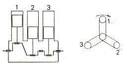
Because the ignition sequence of cylinder 2 and 1 follows each other (ignition sequence 1-3-2), the compression loss on cylinder 2 also affects the oscilloscope trace of cylinder 1. As the piston of cylinder 2 moves upward (and the starter motor needs less effort due to the compression loss), the piston of cylinder 1 also begins to move upward.
Without compression loss, the crankshaft rotation speed would decrease during each compression stroke. However, since the rotation speed at cylinder 2 hasn’t decreased much, it also affects the crankshaft rotation speed of cylinder 1.
With the oscilloscope traces above, the engine’s condition can be assessed. If all peaks are equally high, the relative compression test is satisfactory. In the case of a deviation, these oscilloscope traces cannot determine which cylinder is causing it. To identify this, an ignition measurement can be performed with channel B. This channel can be displayed in the same screen. The ignition trace will appear above the compression measurement line, allowing the correct cylinder to be identified.
Related pages: