Introduction:
Common-rail is an injection system used on diesel engines since 1997. The injectors are controlled by the engine control unit (ECU). Both the opening and closing of the injector (the injection time) and the number of injections per combustion cycle are determined by the ECU. The ECU calculates the injection time based on several factors, such as engine speed, load, ambient air and engine temperature, etc.
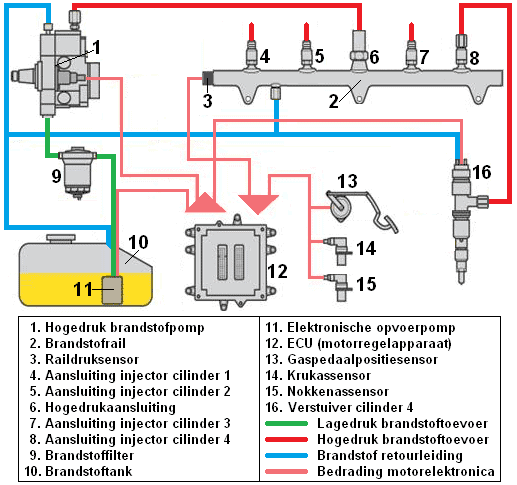
The high-pressure pump supplies the fuel pressure to the fuel rail. A constant pressure is maintained in the fuel rail. All injectors are directly connected to the fuel rail, so the fuel pressure is directly on the supply line of each injector. The injector will only open when it receives an opening signal from the ECU. The pressure from the fuel rail will then enter the cylinder via the injector. The injection stops as soon as the ECU terminates the signal.
The green line represents the low-pressure fuel supply line.
The electronic lift pump (11) pumps the fuel with a pressure of max. 5 bar via the filter element (9) to the high-pressure pump (1). From the high-pressure pump, a high-pressure line (red) runs to the fuel rail. The fuel pressure in the rail depends on the speed of the high-pressure pump. The rail pressure sensor records this value and constantly sends the actual fuel pressure to the ECU.
The high-pressure lines of all injectors are connected to the fuel rail, as shown at fuel rail number 8 and injector number 16. The return line (blue) ensures that all excess fuel from the injector, the fuel rail, and the high-pressure pump is returned to the tank. There is a constant circulation of fuel to cool the components, which are often located in the engine compartment.
Differences between the conventional injection system and common-rail:
In (conventional) diesel engines without common-rail injection (i.e., with a high-pressure line pump, rotary distributor pump, or an electronically controlled distributor pump), the injectors are opened by the pressure of the fuel itself.
The fuel pump rotates with the camshaft speed and builds pressure at the right moment. The pressure build-up and the injection depend on the timing of the fuel pump relative to the camshaft. Therefore, when replacing the timing belt, the fuel pump must also be locked.
In common-rail engines, the fuel is injected when the ECU gives a signal. In the first generation of common-rail engines, the position of the pump did not matter. It could be rotated in any position when installing the timing belt. The pump delivers a constant fuel pressure to the injector rail.
Nowadays, all engines are adjusted much more precisely. The pump often has to be locked to counteract vibrations related to the pump’s pressure build-up. The pumps are now constructed so that the pressure build-up peaks coincide with the engine’s compression stroke. This results in smoother engine operation and less load on the timing belt.
Low-pressure section:
The low-pressure section includes the fuel tank, the electric lift pump, the fuel filter, the low-pressure fuel line, and the return line. These components are described below.
- Fuel tank: stores the fuel. The tank capacity can range between 30 and 70 liters for lighter and heavier luxury passenger vehicles. Click here for more information about the fuel tank.
- Electric lift pump: a0mounted in the tank. This pump ensures that the fuel is pumped from the tank at low pressure to the high-pressure pump (in the engine compartment). In common-rail diesel engines, an electronic lift pump is not always present. Sometimes, a gear pump is built into the high-pressure pump. From the high-pressure pump, fuel is both drawn from the tank and pressure is built up to the fuel rail. Click here for more information about the lift pump.
- Fuel filter: Fuel can contain contaminated particles. These particles are trapped in the filter material so that they do not enter the injection system. The fuel filter also functions as a water separator. Diesel fuel contains moisture, which is very harmful to the pump and the injectors/lines, as it can cause corrosion inside the components. To prevent this, water is also separated from the fuel and remains in the filter. This filter should be periodically drained or replaced. a0
- Low-pressure fuel line: runs from the electronic lift pump to the high-pressure pump. The pressure in this line is about 5 bar.
- Fuel return line: The excess fuel is pumped back to the tank via the return line. The return fuel also provides cooling, as it dissipates heat. Therefore, there must always be return fuel present. When decelerating (braking using the engine), no fuel is injected into the combustion chamber, and the return fuel quantity is greatest.
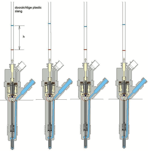
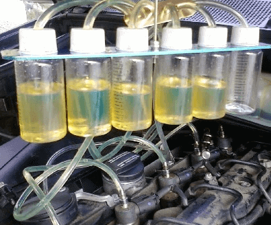
It can also be recognized by the return fuel if an injector remains open unintentionally. This can occur due to contamination, a defect in the injector, or an error in the ECU control. By disconnecting and capturing the return lines of all injectors in separate containers, the differences can be observed. If one injector has significantly less return fuel, it may be that the injector remains open too long, leading to excessive fuel injection. This is shown in the image below, where one injector has no return fuel.
High-pressure section:
The high-pressure section includes the high-pressure pump, the fuel rail, the high-pressure fuel lines, and the injectors.
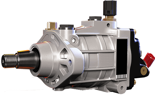
- High-pressure pump
The high-pressure pump is designed as a plunger pump to maintain fuel pressure in the fuel rail (depending on the system) at a constant pressure. This is 1300 bar in the first generation of common-rail engines (since 1997) up to 2000 bar in current systems. Higher injection pressure results in smaller fuel droplets, leading to better combustion and thus lower exhaust gas emissions. The amount of fuel delivered by the pump to the fuel rail is limited as the engine’s needs decrease. The pressure remains approximately constant. By controlling an electromagnetic overloop, a control piston adjusts further due to spring tension, reducing rail pressure. On the page High-pressure fuel pump, the operation of various types of high-pressure pumps, including that of the common-rail diesel, is explained in detail.
- Fuel rail
From the high-pressure pump, fuel is pumped to the fuel rail. A constant fuel pressure is maintained in the fuel rail. Fuel lines run from the fuel rail to the injectors. a0The rail pressure sensor is also connected to the fuel rail (if rail pressure is too high, the engine management will ensure that the overpressure valve opens), and a return line is present.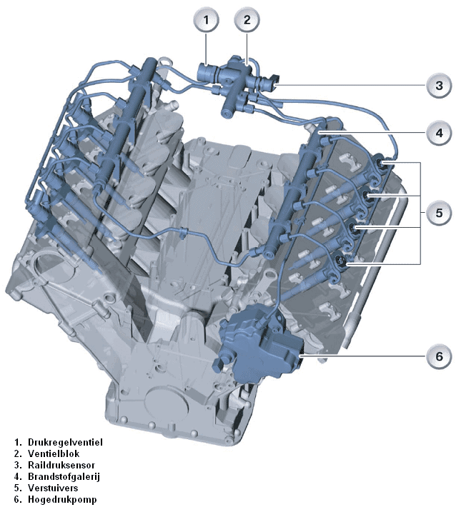
- High-pressure fuel lines
Because high-pressure fuel lines experience high pressures, they must be robust. They are made of metal and connected with flare nuts to both the pump and the injectors. These high-pressure fuel lines transport the fuel from the high-pressure pump to the fuel rail and from the fuel rail to the injectors. The lines between the fuel rail and the injectors are all of equal length and diameter, preventing injection differences. If the distance between the fuel rail and cylinder 1 is greater than between the rail and cylinder 4, a bend is made in the line of cylinder 4. This way, the fuel travels the same distance from cylinder 4 as from cylinder 1. - Injector
Both electromagnetic and piezo injectors are used. These injectors allow control of the injection quantity, curve, and timing. A constant fuel pressure is present at the injector’s inlet, equal to the pressure in the fuel rail. This pressure also prevails in the control chamber as long as the solenoid valve is closed. The solenoid valve is controlled by the ECU.
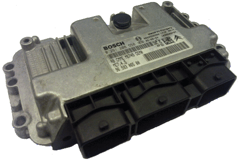
When the solenoid valve is actuated by the engine management, the injector needle lifts, injecting a certain amount of fuel. Because the rail pressure and injector openings are always constant, the engine management knows exactly how much fuel is injected in a specific time. After manufacturing, a minimal deviation still arises, which must be made known to the ECU. After manufacturing, the injector is tested. With the results of, among others, the opening pressure and injection quantity, a code is generated. This code is engraved on the injector and can be read by the technician (see the image below, where the code is 574-221). This method of learning applies to both gasoline and diesel engines.
Measuring voltage and current curves on the electromagnetic injector:
The voltage and current curves on the electromagnetic injector can be measured using an oscilloscope. This helps determine whether the injector is being operated correctly by the ECU.
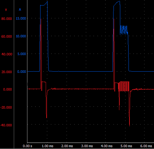
In the scope image below, the red line is the voltage curve, and the blue line is the current curve. a0In the image above, two injections are visible. The left one is the pilot injection, and the right one is the main injection. Other engines may have up to three consecutive injections.
The injector opens with a high voltage and current. The voltage is approximately 80 volts. This high voltage is achieved through a capacitor in the ECU. This high voltage, combined with a low coil resistance, ensures a quick injector response, resulting in a short actuation delay. The current through the coil generates a lot of heat, which must be limited. Without current limiting, the actual current would rise to 300 amperes, a value that would burn out the injector coil long before reaching.
Current limitation is indicated by the voltage that is repeatedly switched on and off, between 4.6 and 5.1 ms. During this current limitation, the voltage (12 volts) and the current (12 amperes) remain high enough to keep the injector needle open.
At 5.1 ms, the actuation is stopped, and the injector needle closes. a0
Engine electronics:
The engine management (ECU) calculates the amount of fuel to be injected and the timing based on sensor data (throttle position sensor, engine temperature, vehicle speed, crankshaft speed, air quantity (mass air flow meter), intake air temperature, exhaust gas quality (NOx)). It is a demanding task to control the injectors. To deliver more than 20 Amperes of current in a short time (max. 300 milliseconds), a voltage up to 80 Volts is necessary.
This is achieved with the charge of capacitors and power amplifier stages.