Check Valve:
A check valve allows fluid flow in one direction unimpeded and blocks fluid flow in the opposite direction.
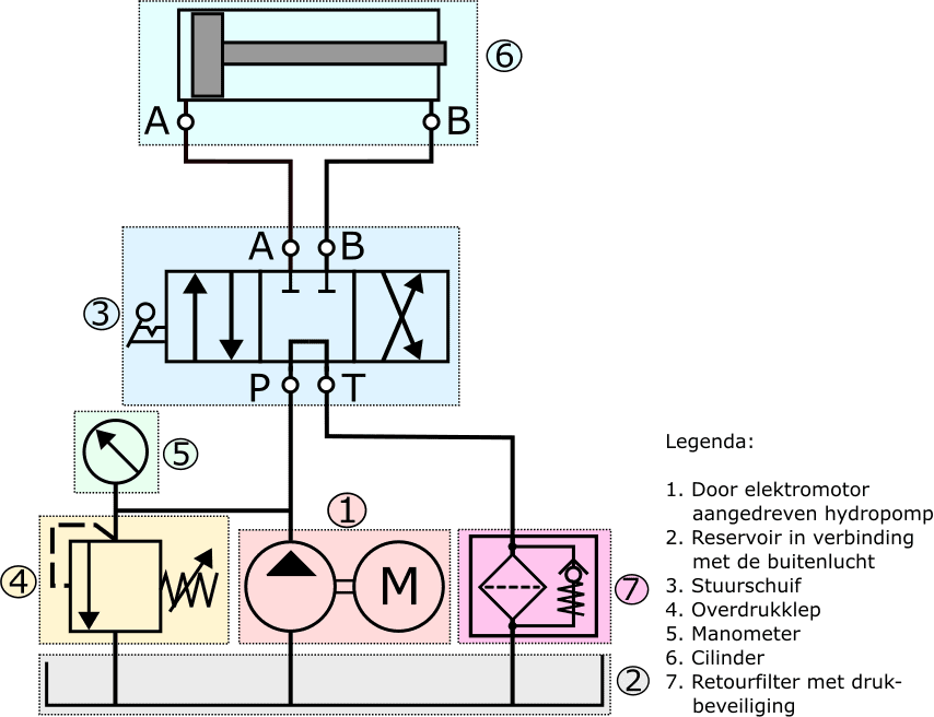
The check valve in the following diagram is located in the housing of the return oil filter. At rest, the spring presses the ball valve onto its seat. When the fluid pressure above the ball valve is sufficiently high to overcome the spring force, the ball valve opens and the fluid can flow past the check valve to the reservoir. The check valve here serves as protection against excessive pressure, which can occur when the filter element becomes so contaminated that the fluid flow is impeded.
The check valve is also found as protection in hydraulic systems of, for example, a dump truck. The valve is mounted in the hydraulic cylinder and prevents the load bed from descending uncontrollably in case of sudden hose rupture. Instead, the ball immediately shuts off the volume flow due to back pressure, causing the cylinder with load to stop immediately.
We find the check valve not only in safety systems but also in circuits where we want hydraulic oil to flow through a component in one direction. An example of this is seen in the following image.
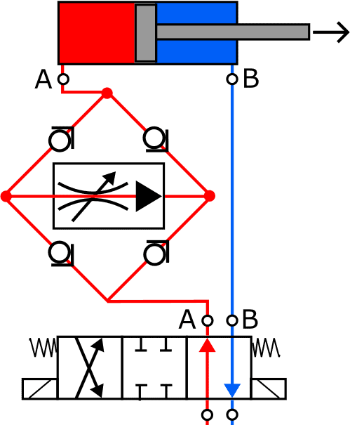
Between the control slide and the supply of the cylinder, we see a flow control valve in a Graetz circuit. This circuit allows the fluid to flow in the arrow direction through the flow control valve, regardless of how the cylinder is operated. The flow control valve operates in only one flow direction, and such a circuit prevents multiple flow control valves in one line.
When the piston extends, the check valves in the lower left and upper right are pushed off their seat to allow fluid flow. The other two check valves remain closed.
When the control slide is set in the extreme right position, the fluid flow direction to and from the cylinder reverses. The return fluid exits the cylinder and pushes the ball valves in the upper left and lower right off their seat to flow – via the control slide – to the reservoir.
In both situations, the fluid flows in the arrow direction through the flow control valve.
Counterbalance Valve, Brake Valve:
The counterbalance valve, also known as a brake valve, is a precisely controlled check valve. It is suitable for allowing a large load to decelerate in a controlled manner. The counterbalance valve is used in smaller cranes, such as truck-mounted cranes.
The counterbalance valve is essentially an extension of a “normal” check valve. The difference between these two valves is that the controlled check valve must be opened against the load pressure, making it dependent on and sensitive to the load pressure. The normal check valve is susceptible to jerky movements, whereas the counterbalance valve is not. With the counterbalance valve, the required pilot pressure depends on the pre-set spring pressure.
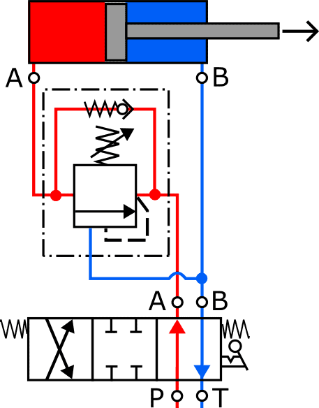
The hydropump, pressure relief valve, and filter are omitted from this drawing for simplicity. The control slide is in the correct position to extend the cylinder. The fluid flows via the check valve (in the counterbalance valve) to the cylinder.
After switching the control slide (extreme right position), the cylinder is retracted. The oil is now supplied to the rod side (via connection B). The built-up pressure opens the counterbalance valve. The oil flows via the counterbalance valve back to the reservoir.
At the moment the cylinder descends faster than oil is supplied to the rod side (this is called overtravel), the pressure on the rod side and thereby the pilot pressure on the counterbalance valve decreases. Consequently, the valve is pushed towards “closed” by the spring. As a result, the volume flow decreases and comes into balance with the volume flow supplied on the rod side.
The counterbalance valve can also act as a pressure relief when the user is overloaded by external forces or by suddenly operating the control slide: when the control slide is suddenly set in the center during the cylinder’s descent, the counterbalance valve closes immediately. The pressure then built up in the cylinder reopens the counterbalance valve from the cylinder side. This limits the pressure in the cylinder.
Related page: