Introduction:
We discuss a real fault that can be encountered in practice with a case study. To troubleshoot, one must have the knowledge and skills to operate diagnostic equipment, consult wiring diagrams, take measurements with test equipment, and evaluate measurement results. Therefore, firstly study the following pages:
- OBD diagnosis;
- Reading wiring diagrams;
- Sensor types and signals (passive, active, and intelligent);
- Troubleshooting sensor wiring;
- Measuring with the multimeter and oscilloscope.
Reading the fault memory:
In this case, we address a car with a loss of power. The engine warning light is on.
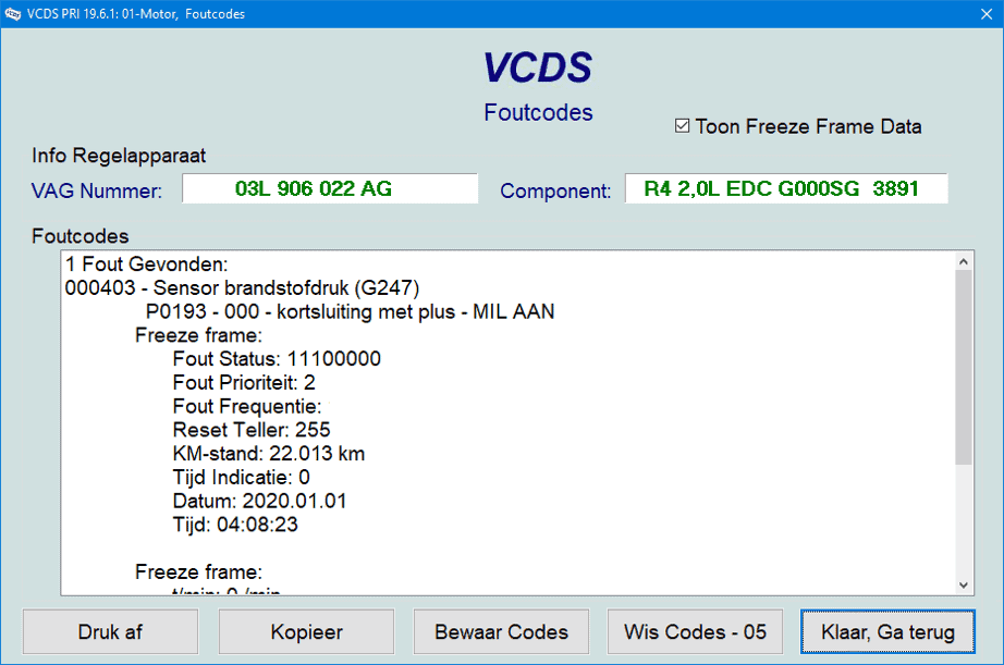
When a customer complains and/or warning lights are on, we first start by reading the car. The following fault is active:
P0193 – fuel pressure sensor G247 – short to positive.
The fault returns immediately after clearing. It is therefore permanently present.
Looking up the wiring diagram:
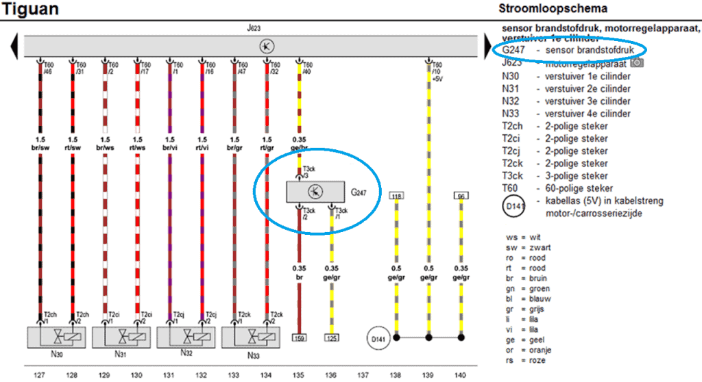
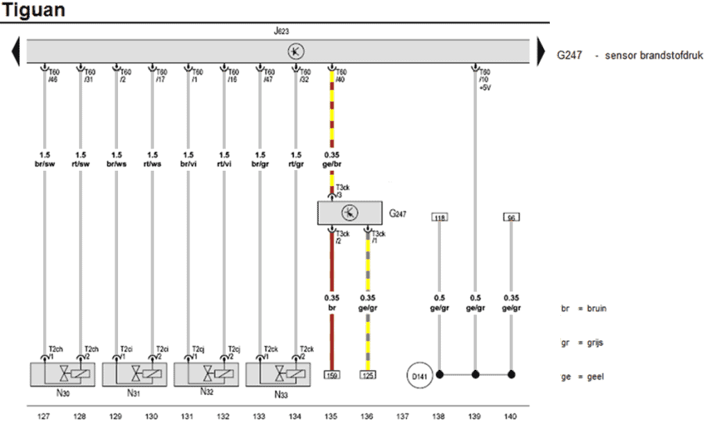
We locate the fuel pressure sensor with component code G247 in the wiring diagram. The sensor has a three-pin connector (T3ck). The yellow/brown wire (pin 3 of the sensor) is connected to pin 40 on the engine ECU (J623). This is the signal wire. The other two wires (pin 1 and 2) go via references 159 and 125 to other locations in the diagram.
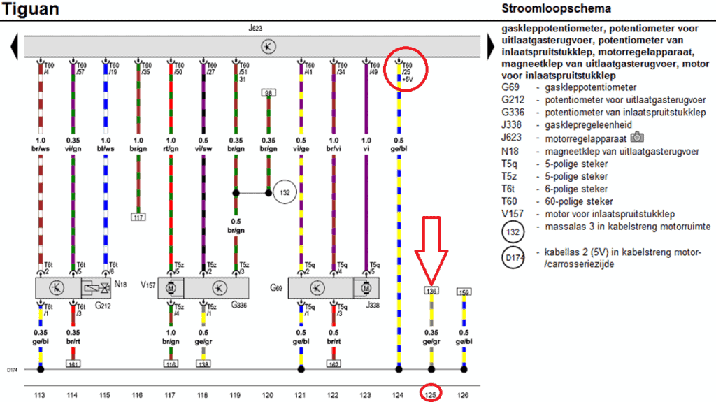
We look up coordinate 125 to trace the yellow/gray wire. The next diagram shows that the yellow/gray wire is connected to junction D174 (5-volt supply line) which is connected to several components. The supply line ends up with the yellow/blue wire at the ECU on pin 25. This is the power supply wire for the fuel pressure sensor, among others.
We return to the fuel pressure sensor diagram. We know that pin 1 is connected to the common positive for the sensors.
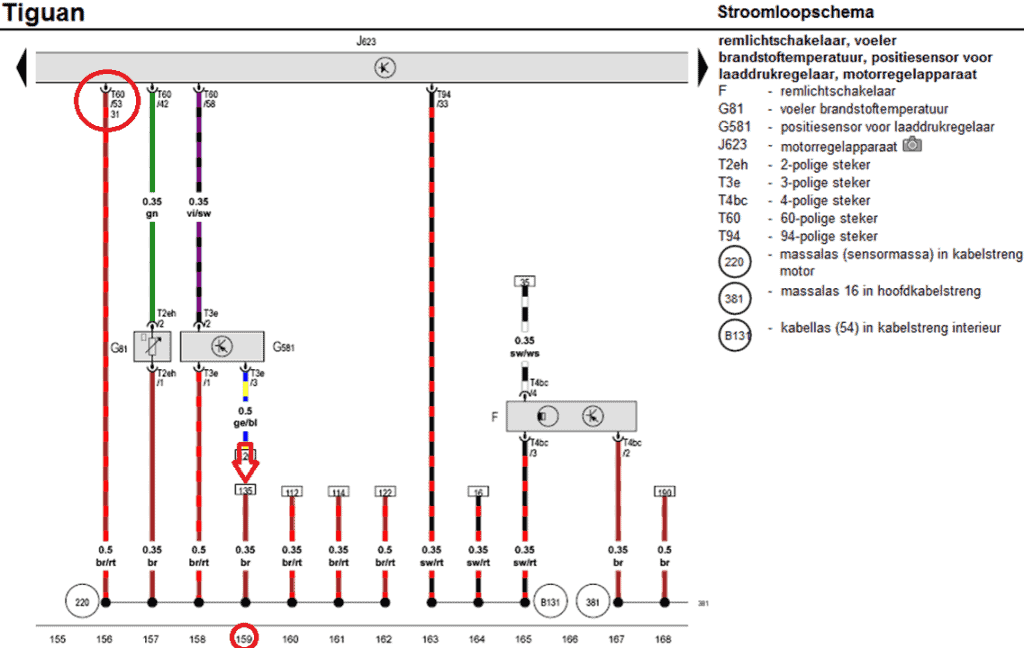
We now follow reference 159 and end up in the next diagram. The brown wire leads to a ground junction and is connected to pin 53 of the ECU.
We return to the original diagram and focus on the fuel pressure sensor. The wires we do not use are grayed out.
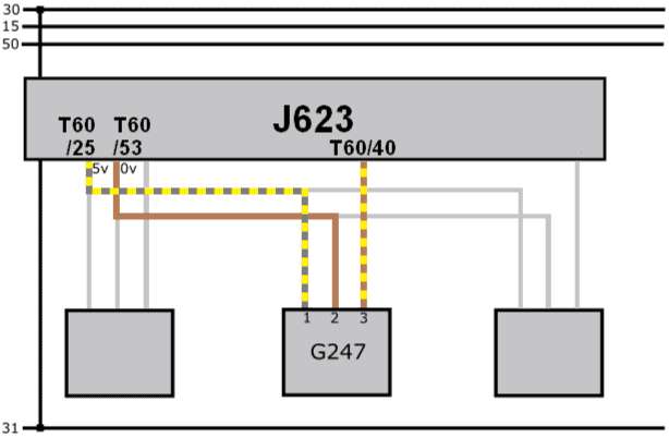
The original wiring diagram contains references: this can cause confusion. For that reason, we create a simplified diagram. It shows the common power supply and ground (pins 25 and 53) and the signal wire (40).
Measuring with a multimeter:
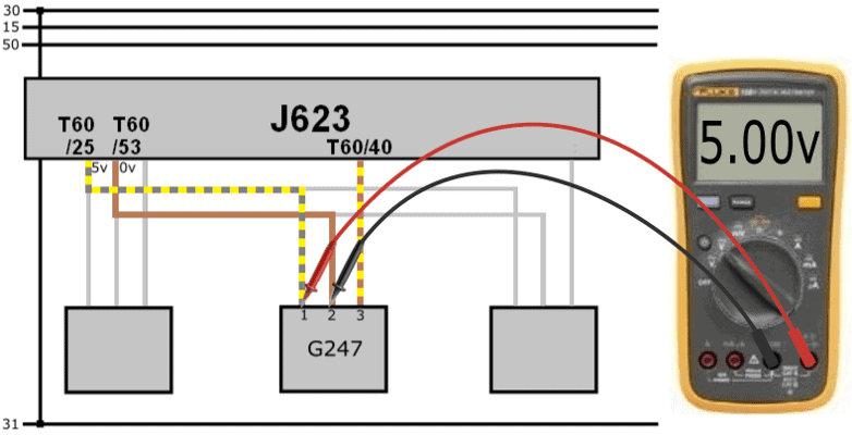
With the voltmeter, we measure the power supply voltage relative to ground. The multimeter displays 5.00 volts on the screen: this indicates that both the positive and ground wires are in order.
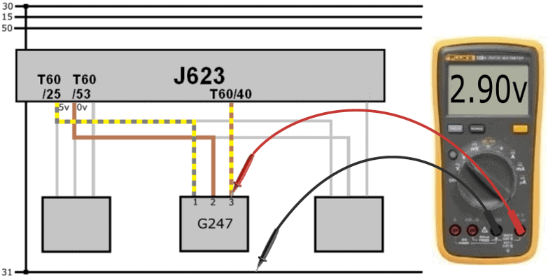
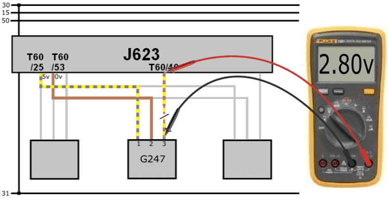
The signal voltage (measured relative to ground) is 2.9 volts. This value is realistic: based on this voltage, we cannot conclude that there is a short to positive.
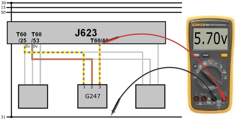
The 2.9-volt sensor signal is sent to the ECU. However, we measure a voltage of 5.7 volts at the ECU.
The voltage on the ECU side is higher than the voltage output by the sensor.
With a voltage difference over a wire, there may be a transitional resistance. In principle, the voltage at the sensor side should be higher; however, now the voltage on the “receiving” side is higher.
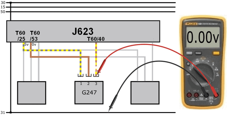
The connector is removed from the sensor. Upon measuring in the connector, we measure 0 volts.
The voltage difference of 2.8 volts can be explained:
- We measure a voltage of 5.7 volts on pin 40 of the ECU due to the internal circuitry;
- The sensor transmits a voltage of 2.9 volts;
- The voltage difference between the sensor and ECU is: (5.7 – 2.9) 2.8 volts.
- With the connector removed, we measure 0 volts in the connector, but still 5.7 volts on the ECU side.
- Conclusion: the signal wire is interrupted.
The wire break was located in a part of the wiring harness that was not fixed to a rigid point. During a previous disassembly, the wiring harness bracket was broken. The wiring harness was allowed to move considerably for an extended period. Eventually, the signal wire chafed through. After repairing the signal wire and some other slightly damaged wires, the wiring harness bracket was properly fixed, and the fault did not reoccur after clearing.
Why we’re measuring a voltage of 5.7 volts:
In the following image, the circuitry in the ECU is shown. The signal from the active MAP sensor is sent via the blue wire to pin 40 of the ECU. Inside the ECU are several resistors (R1, R2, R3) and a capacitor (C). a0The sensor signal wire is connected between resistors R1 and R2 in the ECU.