Introduction:
Automakers produced new gasoline engines up to the early 1990s with fuel supply regulated by a venturi carburetor. The carburetor is located on the intake manifold of the engine. In the carburetor, the supply and mixing of gasoline and air occur.
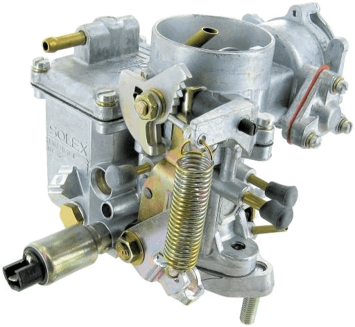
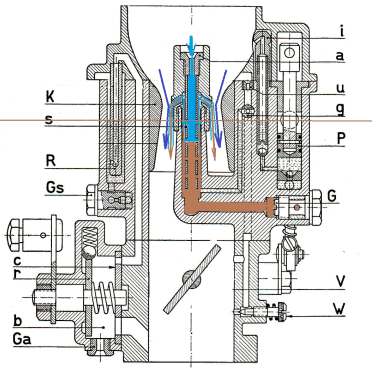
The image shows a Solex carburetor, which was used, among others, on the VW Beetle. Other well-known carburetor brands are: Zenith, Stromberg, Weber, Rochester, Holley, Binks, Carter, and S.U.
Engines equipped with a carburetor could no longer meet the requirements of the latest emission standards (Euro 1) at the time. Since then, the carburetor has been replaced by the computer-controlled engine management system, which continues to be developed to this day.
Because new cars have not been equipped with a carburetor for almost three decades, this topic is often not included in the teaching materials of current automotive technology courses.
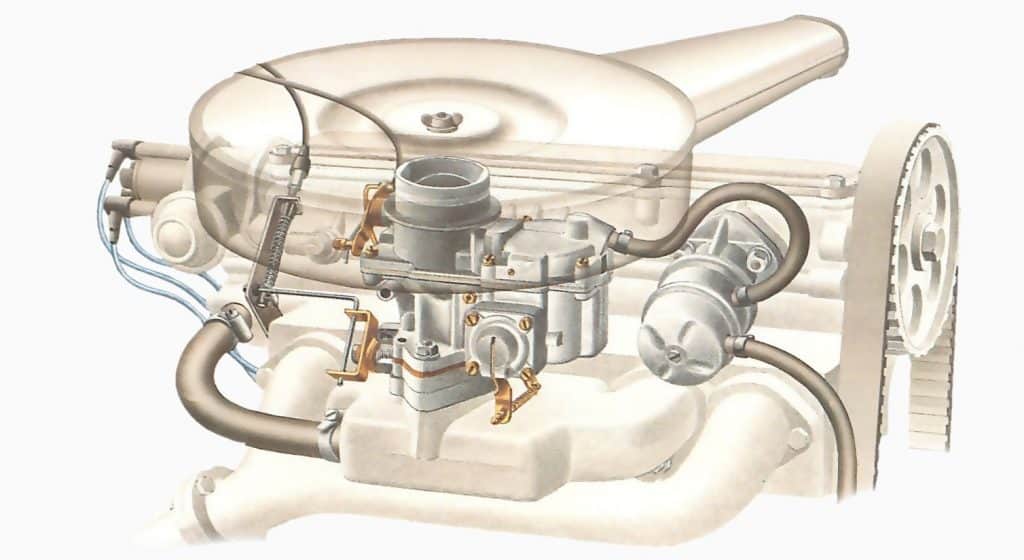
The carburetor is positioned between the intake manifold and the air filter.a0The image below shows the position of the carburetor on the engine.
Different types of carburetors:
The way the carburetor is mounted on the engine affects the flow direction. The image below shows the downdraft (left), updraft (center), and sidedraft carburetor (right).
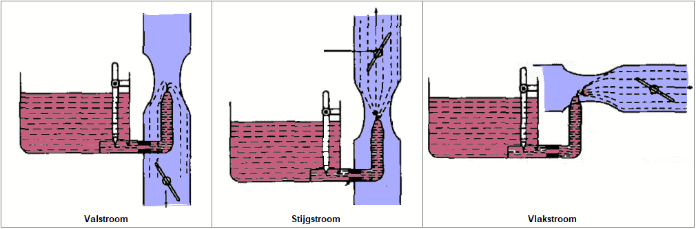
- Downdraft: air enters at the top and flows downward. The fuel flows with the air direction and with the help of gravity to the cylinders. This type is the most commonly used.
- Updraft: the airflow is in an upward direction. The weight of the fuel results in a less easy flow than with the downdraft carburetor. This type was no longer used in the last years of the carburetor era.a0
- Sidedraft: is positioned in a horizontal direction.
Main section:
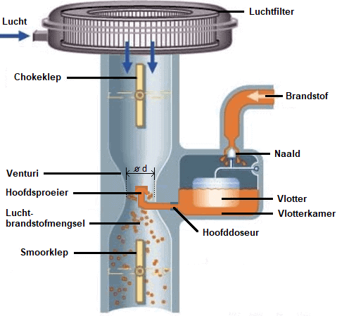
A mechanical fuel pump supplies the carburetor’s float chamber with gasoline. Due to the rising fuel level and the floating float element, the inlet is sealed with the needle. The needle opens the intake when the fuel level drops.a0From the float chamber, the gasoline reaches the main nozzle through the main jet. The fuel level in the main nozzle is kept below the nozzle opening by the level in the float chamber. If the needle does not close properly (due to a defect or contamination), the fuel level in the float chamber becomes too high, causing excess fuel to flow through the main nozzle into the engine.
The throttle valve is connected to the accelerator pedal. The opening angle of the throttle valve affects the vacuum and airspeed in the venturia0(constriction in the intake pipe). The amount of gasoline drawn from the main nozzle depends on this vacuum.a0A higher airspeed creates a higher vacuum, adding more gasoline to the air. The optimal fuel/air ratio depends on the size of the main jet in relation to the venturi diameter. The main jet size is suitable for a very limited RPM range.a0The mixture amount determines engine torque.
The relationship between increasing airspeed and the corresponding vacuum and the outflow of gasoline can lead to mixture enrichment and continuous increase. The bleeder with compensating air regulation compensates for this. Mechanically, the compensating air system tries to maintain a stoichiometric air-fuel ratio. The holes in the air bleed pipes serve to prevent enrichment and maintain a stoichiometric mixture. The air bleed holes have different diameters.
- Low RPM: vacuum is relatively low, gasoline flows from the main jet out of the main section.
- Higher RPM: vacuum increases, more gasoline is drawn than the main jet can supply, limiting the fuel flow. The level in the mixing pipe drops, exposing the first air holes in the mixing pipe. The air from the air jet is mixed with the gasoline.
Due to the added air, the vacuum decreases, slowing the fuel flow. The higher the RPM, the more air holes are exposed, and more compensating air mixes with the gasoline. At very high RPMs, the pipe may be completely empty, and air from the idle section is drawn in.a0
Cold start:
To achieve a sufficiently rich mixture during starting, we see two configurations:
Configuration with choke valve:
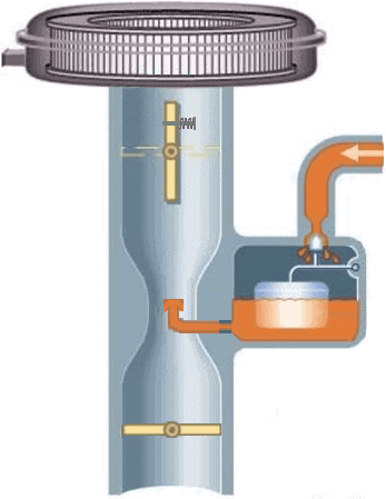
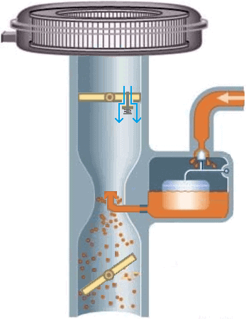
The explanation pertains to the two images below. The choke valve is located at the top of the carburetor. In the choke valve, there is a hole that is normally closed with a spring-loaded valve. When starting a (cold) engine, the choke valve can be manually closed. The vacuum “sucks” the valve open, allowing air to be drawn in. The small air opening creates a large vacuum in the main section during starting, drawing in gasoline. However, the throttle valve must be partially open; otherwise, no vacuum is present at the main nozzle. A linkage between the two valves enables simultaneous operation, without having to use the accelerator. After the engine starts, the choke can be opened again. In warm outside temperatures, this can happen sooner than in freezing temperatures.
Configuration with starting carburetor:
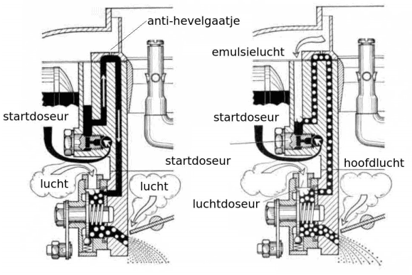
The starting carburetor does not use a choke valve but has a separate fuel supply section. The image below shows a carburetor of this type.
In a cold start, the throttle valve must be closed. When the driver operates the choke button, a slide in the carburetor rotates, and openings connect to the carburetor’s starting section. Gasoline is drawn from the start jet and mixes with the incoming air in the air jet. The vacuum under the throttle valve draws the air/fuel mixture inward. In this situation, the throttle valve is still closed. After the engine starts, the higher vacuum draws the fuel pipe empty from the start jet. The emulsifying air provides extra air to prevent an overly rich mixture.
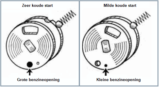
The operating slide can be equipped with two flow openings with different diameters. The driver can then choose between a very cold start, a mild cold start, and letting the engine warm up.
Idle and progression circuit:
While idling, the throttle valve is closed, and a high vacuum exists below this valve. Due to the small airflow, there is insufficient vacuum in the venturi to draw fuel from the nozzle. However, a high vacuum exists under the throttle valve. In this situation, an additional fuel channel below the throttle provides the engine with the correct amount of gasoline. The image is of a Solex carburetor.
The adjustment screw to modify the mixture amount affects the CO value. The idle speed should be adjusted with the throttle adjustment screw.a0
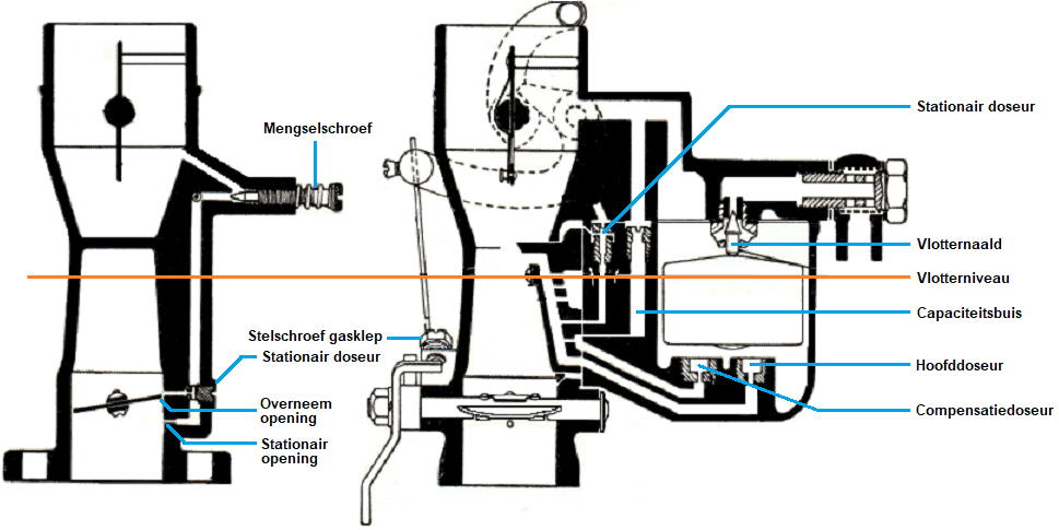
The image below shows the idle (left) and main sections (right) of a Zenith carburetor. The Zenith shares many similarities with the previously described Solex carburetor.
The idle opening is located below the throttle valve, and the progression opening just above it. When the driver starts accelerating, the progression section supplies extra fuel. Then, the main section takes over. The main section also supplies fuel during idling. The fuel passes through the idle jet and the adjustable mixture screw. A second idle jet is mounted at the throttle valve. The speed should be adjusted with the throttle adjustment screw. The main jet and the compensating jet are both mounted at the bottom of the float chamber and form the main section. The capacity bus serves as a reservoir and is filled with gasoline.a0
Acceleration:
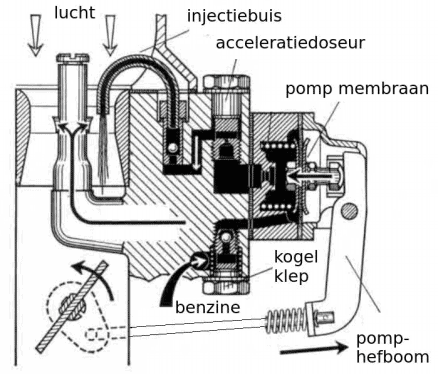
A Solex carburetor is equipped with a mechanically or pneumatically operated accelerator pump. During rapid pressing of the accelerator pedal, a richer mixture is needed for a good mixture ratio and more power. The spring is tensioned and moves the pump diaphragm to the left. The fuel is injected into the venturi via the diaphragm and the accelerator jet.
The ball valves ensure the suction and expulsion of the fuel, depending on the spring force. The tension can be manually adjusted.
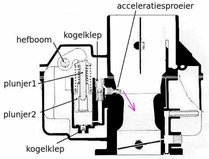
The following image shows the mechanically operated acceleration section of a Zenith carburetor. The inner plunger is pushed down while pressing the accelerator pedal. The fuel injection takes place via the accelerator nozzle. The spring of the outer plunger is tensioned, so the injection duration depends on the – gradually relaxing – spring tension. Not the position of the lever, but the spring tension determines the injection time. Two ball valves ensure – just like the Solex carburetor – the suction and expulsion of the fuel.
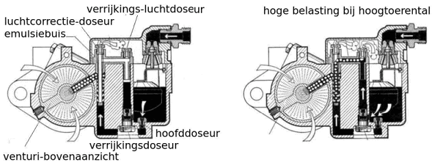
Full load:
The mixture must also be enriched at full load and higher RPMS. The carburetor can be equipped with a separate enrichment section, which is part of the main section. During part load, only the main section provides fuel. Higher load and higher RPMs cause more vacuum in the venturi. This vacuum draws extra fuel through the enrichment jet (see image).