EnglishEN
  • NederlandsNL
MVWautotechniek.nl
  • Internal Combustion Engines
  • Electric Drive
  • Body
  • Comfort, Safety, HVAC
  • Electronics
  • Chassis
  • Transmission
  • Diagnostic Techniques
  • Other
  • Search
  • Internal Combustion Engines
  • Electric Drive
  • Body
  • Comfort, Safety, HVAC
  • Electronics
  • Chassis
  • Transmission
  • Diagnostic Techniques
  • Other
  • Search

Capacitor

Topics:

  • Introduction
  • How the Capacitor Works
  • Series Configuration
  • Parallel Configuration
  • Capacitive Level Sensor
  • Charge and Discharge Time of the Capacitor (RC Time)
  • Charging the Capacitor (with Known Charge Time)
  • Discharging the Capacitor
  • Charging the Capacitor (with Known Final Voltage)

Introduction:
Capacitors are used in electronic devices such as computer circuit boards, televisions, and radios, but on this page, we apply the concept of ‘capacitor’ to automotive technology. In automotive technology, capacitors can be found in, for example, electronic filters, control devices, level meters, ignition coils, and relays.
A capacitor stores energy. This energy can serve as interference suppression in a radio filter (the capacitor filters certain frequencies, such as dynamo noise), or as a turn-off delay in the interior lighting. When the door is closed, the interior lighting fades out slowly. Voltage fluctuations from rectifiers (diodes) are also smoothed out by capacitors. The capacitor can charge and discharge in a short time.

How the Capacitor Works:
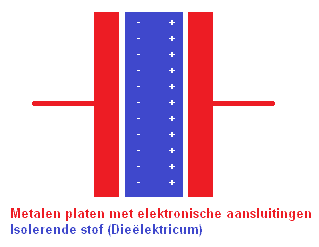
A capacitor consists of 2 (usually metal) conductors separated by the dielectric. This is a non-conductive material such as plastic, or otherwise by a vacuum.
When an electronic voltage source is applied to the plates, both plates will be charged. The left plate (with the -) will be charged negatively, and the right plate (with the +) positively.
The charging current stops as soon as the voltage difference between the plates is equal to the voltage difference of the power source. This charging takes time. This time can be calculated. This will be addressed later on the page.

The charging current stops as soon as the voltage difference between the plates is equal to the voltage difference of the power source. This charging takes time. This time can be calculated. This will be addressed later on the page.

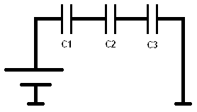
Series Configuration with Capacitors:
In capacitors connected in series, the charge on all capacitors is equal.

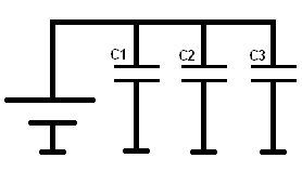
Parallel Configuration with Capacitors:
In parallel-connected capacitors, the voltage across all capacitors is equal.

Capacitive Level Sensor:
This example concerns the level sensor in a car’s fuel tank. There is a shared dielectric.
The principle of capacitive level measurement is based on the change in capacitance of the capacitor, which depends on the change in level (in this case, the fuel quantity).
Gasoline is not a conductive substance, so no short circuit can occur between the plates of the capacitor due to conduction, as would be the case with, for example, water.

The capacitance of the capacitor can be determined with a formula. The meanings of the symbols are as follows:

  • C = capacitance
  • A = plate area
  • d = distance between the plates

The diagram shows that the tank is 40% filled with gasoline. The remaining 60% is vapor.0The gray bar is the capacitive capacitor with distance S (between the plates). Using the general formula, the capacitance, and thus the tank level, can be determined.

Data:

Dielectric constants:
b50 (vacuum) = 8.85 x 10⁻¹² (power to the negative twelfth)
b5R gasoline = 2.0
b5R vapor = 1.18

The area (A) of this capacitor is 200mmb2 (length x width). The distance between the electrodes (S) is 1.2mm

Because the tank is 100% filled, we assume that the dielectric constant of gasoline (2.0) works over the entire area of the capacitor (200mmb2). When the tank is no longer 100% filled but 40% (as in the diagram above), the total area of the capacitor must be divided into percentages (40% and 60% to make 100 together). There is 40% for gasoline and 60% for the vapor. Therefore, two formulas need to be made (C1 and C2):

The formulas show that at 40% gasoline, the capacitor is charged to 1.18 pF and at vapor 1.04 pF. Because the 40% and 60% must be added together to make 100%, the values of the capacitor must also be added.
This can be done as follows: 1.18 + 1.04 makes 2.22 pF.

This 2.22 pF is transmitted to the fuel gauge on the dashboard and, among other things, the ECU.

Calculator:
Instead of filling in the formula each time, the data can also be entered into the calculator. It then calculates the capacitance of the capacitor automatically. It is also very handy for checking the calculated answer!
Click on the image below to start the calculator. It opens in a new window:

Charge and Discharge Time of the Capacitor (RC Time):
First, the concept of Tau is explained:
As soon as a capacitor is placed in series with a resistor, the capacitor will charge to the applied voltage (the source voltage or battery voltage). It is established that the capacitor is charged to 63.2% of the applied voltage after 1 (Tau). At 5, the capacitor is 99.3% charged. (Theoretically, the capacitor will never be fully 100% charged). This is illustrated in the following diagram:

The charging of the capacitor is shown in the graph above. At t0, the capacitor switches on, and at t0 + 5, it is charged.
At time t0+ (on the x-axis), the capacitor is exactly 1 charged because it was switched on at time t0. On the Y-axis, this is seen as 63.2% of Uc. At time t0+5, the capacitor is 99.3% charged.

With the formula = R x C, the number (Tau) is calculated.

In the circuit below, 2 resistors are in series with each other. Thus, the total resistance is R1+R2. This makes 10+10=20k. (20×10^3). Multiplied by C of 10 Microfarads (10×10^-6) results in (200×10^-3) = 0.2.
This 0.2 must later be filled in during the calculation.

R1 = 10k
R2 = 10k
C = 105b5

Both the resistance values and the capacitance of the capacitor determine the charge and discharge time of the capacitor. The speed at which the capacitor needs to charge and discharge can be very important. Especially in microprocessor circuits, this time must be very short. In the delay of the interior lighting of the car, the time may be longer. The general formula for switching times is as follows:

Uct stands for the voltage at a particular time. This time is calculated in the formula. Uct 0 is the initial voltage, where charging or discharging begins. Uct ~ (symbol for infinity) stands for the maximum voltage it can reach (that is the applied voltage / battery voltage). The e stands for the e-power. This is a natural logarithm. It is an exponential number. The -(t1 – t0) divided by 3c4 (Tau) is now in exponent form. It must also be pronounced and calculated as e to the power of -(t1 – t0) divided by 3c4.
Then follows + Uct ~. This is again the applied voltage / battery voltage.
After performing this calculation, an answer in volts (voltage) is obtained.

The next section provides an example with a circuit:

Charging the Capacitor (with Known Charge Time):
In the image, the switch is closed. A current flows from the battery via the resistors to the capacitor. We want to calculate the voltage when the capacitor has been charged for 200 milliseconds (200 x 10^-3).

U = 10 v
R1 = 10k
R2 = 10k
C = 10 45F (Microfarad).

3c4 = R x C
3c4 = (10,000 + 10,000) x 0.000010 = 0.2
3c4 = 200 x 10^-3

In formula form, this becomes:

From t0 to t1, the capacitor is charged to 6.3 volts.0This is equal to 13c4 (since at 1, the capacitor is 63.2% charged). Based on the calculation, the graph looks as follows:

Discharging the Capacitor:
Now we will discharge the capacitor. The switch in the circuit is moved from position 1 to position 2. The power source (the battery) is disconnected from the capacitor’s circuit. In the circuit, both sides of the capacitor are connected to ground (via resistor R2). The capacitor will now discharge. Again, the resistance value and the capacitance of the capacitor determine the discharge time, just as it did with charging. However, there is now one less resistor (since R1 is no longer in the same circuit). Therefore, the discharge time will now be shorter than the charging time:

Now, we fill in the formula again to calculate the Tau:
3c4 = R x C
3c4 = 100,000 x 0.001
3c4 = 100

According to the formula, the capacitor is discharged to 2.32 volts after 100ms. If we did not measure t1-t2 over 100ms but over 200ms, the graph would almost reach 0 volts again. Charging takes more time than discharging because, during discharging, there is 1 resistor in the circuit, unlike when charging, where 2 resistors are connected in series. Therefore, the capacitor will essentially need more than 200ms to reach 0 volts. If the switch is flipped back to position 1 at t2, the capacitor would immediately begin charging again.

The discharge period can then be plotted in the graph:

Charging the Capacitor (with Known Final Voltage):
In the example above, the charge time (of 200ms) was known for charging the capacitor. With the given data of initial-final voltage, charge time, and the number of Tau, the final voltage could be calculated. The capacitor was then charged to 6.3 volts after 200ms.
Now we find ourselves in a situation where the charge time is unknown, but the final voltage is already given. For convenience, we use the same example;
(The resistance values and the type of capacitor are the same as in the first example).

R1 = 10k
R2 = 10k
C = 105b5F (Microfarad).

3c4 = R x C
3c4 = (10,000 + 10,000) x 0.000010 = 0.2
3c4 = 200 x 10^-3

What we want to know now is, how much time does it take (from t0 to t1) to charge the capacitor to 6.3 volts?

Filling in the known data into the formula of the 1st order differential equation does not directly yield an answer. The formula must be rearranged, as -(t1 – t0) is unknown, and we essentially want to know that.

Explanation: First, the basic formula is established. We fill it in with the data that is known. Because we want to know the time at a charge time of 6.3 volts, we fill this in at the beginning of the formula. The (t1 – t0) remains noted as is.
Next, we divide the Uct~ of 10 v by the 6.3 v on the left side of the formula, resulting in an answer of 3.7 v. The +10 can now be crossed out.
The next step is to eliminate the -10 (number for the e-power). By dividing the -3.7 by -10, it cancels out. On the left side of the formula, we now fill in 0.37.

Now, it is time to eliminate the e-power. The inverse of an e-power is the ln, a natural logarithm, (just as the inverse of a power is the root).
By entering the formula into the calculator with the ln button, the answer -0.200 is obtained. Because the negative signs are present on both sides of the = sign, they can be crossed out.
The answer comes out as 200 ms. Thus, it takes 200 ms for the capacitor to charge to 6.3 volts. This is correct because, in the first charge time calculation, this was a given, which was used to calculate the 6.3 volts.
With this formula, the time at, for example, 3 volts can also be calculated. Then change the 6.3 volts to 3 volts, subtract 10 volts from it, divide it by -10 volts, multiply it with the ln and the 200 . 10^-3. An answer of 71 ms is then obtained.

  • Home
  • About
  • Disclaimer
  • Copyright
  • Statistics
  • Projects
  • Workshop
  • Search
  • Home
  • About
  • Disclaimer
  • Copyright
  • Statistics
  • Projects
  • Workshop
  • Search

Copyright 2025 © MVWautotechniek.nl
Designed, written and hosted by Marco van Wijk