Introduction:
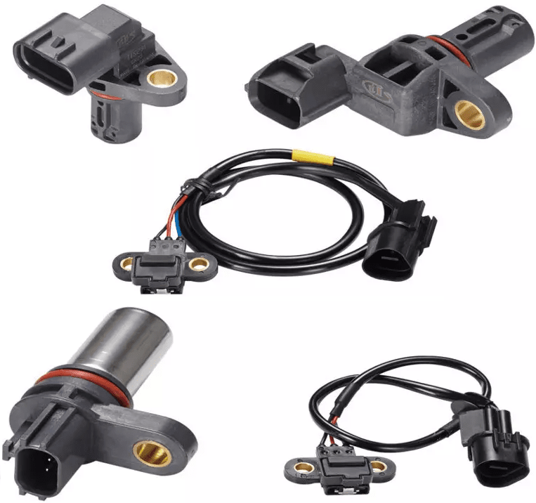
Internal combustion engines can be equipped with one or more camshaft position sensors. These position sensors measure the pattern of the reference disc (rotor) which is mounted on the side of the camshaft, or from the pattern of a section in the longitudinal direction of the camshaft.
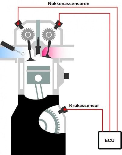
The signal from the camshaft position sensor is an addition to the crankshaft signal for the engine management system:
- The crankshaft position sensor is used to determine the engine speed and crankshaft position;
- Based on the signal from the camshaft sensor, the engine management system can determine with which stroke the piston is moving from BDC to TDC.
The camshaft is often designed as a Hall sensor and receives a power supply and ground from the ECU. The signal, in the form of a block voltage, is sent to the ECU via the signal wire.
Advantages of an Engine with Camshaft Position Sensor:
Not all engines with an engine management system and computer-controlled injection and ignition are equipped with camshaft sensors. However, camshaft sensors allow for the following enhancements:
- Individual control of injectors and coils: without a camshaft signal, there is no individual control of coils and injectors, because the crankshaft signal is not sufficient: every work cycle consists of two crankshaft rotations and only one camshaft rotation. Engines without a camshaft sensor use a DIS-coil where the spark plugs fire every crankshaft rotation and group-wise injection;
- Camshaft adjustment: to obtain extra torque, or specifically for regeneration purposes (diesel engines with particulate filters), the ECU must be able to read the position of the camshaft to properly control the camshaft adjustment;
- Error recognition: with problems related to distribution timing, a deviation in the crank-to-camshaft ratio is recognized. An error description might state: “incorrect assembly combination” or “crankshaft and camshaft signal ratio outside tolerance.”
Location of the Camshaft Position Sensor in the Cylinder Head or Valve Cover:
There are several ways the camshaft sensor reads the position of the camshaft:
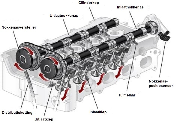
- By a cam pattern on the camshaft: the sensor is usually located on the valve cover, near the timing belt, or screwed onto a separate housing of the camshaft, as shown in the drawing below;
- On the camshaft is a trigger wheel (alternative names: reference disc, position disc, rotor with notches and cutouts of various sizes). In that case, the camshaft sensor is screwed into the cylinder head.
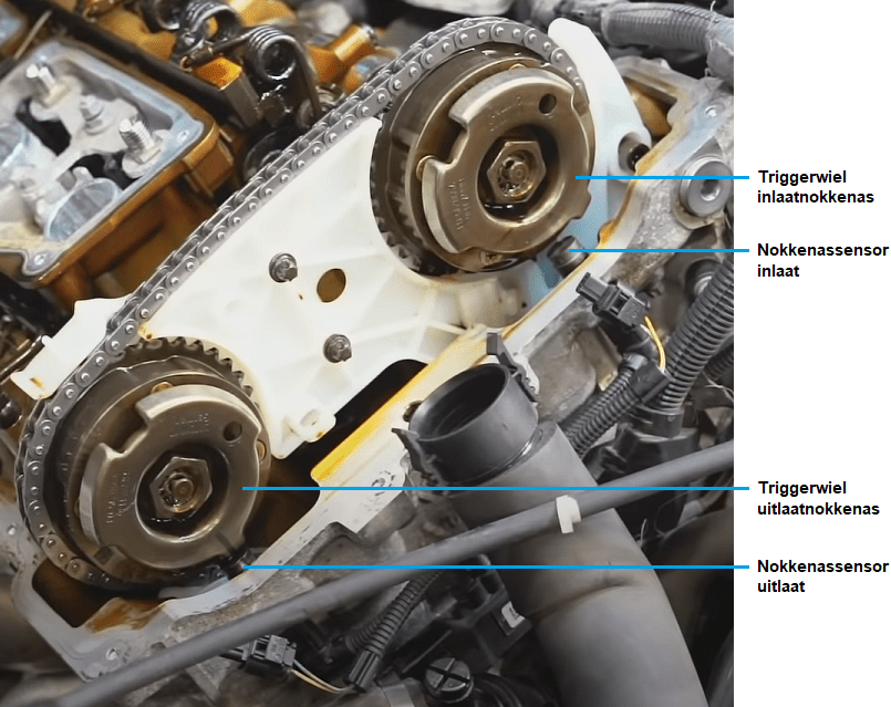
The following image shows a BMW engine with a new timing chain and guides installed. The trigger wheels (reference wheels) are separate discs clamped against the camshaft with the central bolt. The trigger wheels have multiple notches and cutouts of different sizes. Both camshaft sensors (positioned directly below the trigger wheels) read the course of the notches and cutouts of the trigger wheels.
Using the pattern of the trigger wheels, the engine management system can determine, within one camshaft revolution, which cylinder is starting the compression stroke. The system can then set the injection and ignition to start the engine. The engine will start after a short period of cranking.
Measuring the Signal from the Camshaft Sensor with the Oscilloscope:
If a camshaft sensor is defective, a DTC (diagnostic trouble code) is usually stored. Using an oscilloscope, we can measure the camshaft signal while starting or running the engine. Typically, we measure the camshaft signal simultaneously with the crankshaft signal to check the timing of the distribution. This method is explained on the page about the crankshaft position sensor.

Related pages: