Cam Height Measurement:
The cams of the camshaft can wear out due to age or lack of lubrication. This reduces the cam height. Complaints associated with worn cams may include:
- The fuel trims indicate a negative percentage: the injection quantity is corrected (reduced) due to a shortage of air;
- Reduced power: the maximum torque cannot be achieved due to a lack of air. If all cams are equally worn, the engine may still idle smoothly;
- Irregular engine operation: this occurs especially if only one or a few cams wear out while the others are still in good condition.
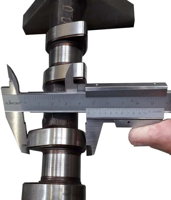
The cam height can be determined using a caliper. Alternatively, a micrometer can be used for greater accuracy. To determine the cam height of a single cam, we take two measurements, as shown in the figure.
- A = base circle diameter;
- B = total cam height;
- C = actual cam height / lift height.
The cam height (C) of the camshaft is the difference between size A and B.
The cam heights of the intake and exhaust camshafts are different. Cam heights on a single camshaft should not differ from each other. We must consider tolerances, however. Only when the measurement falls outside the tolerances is the camshaft rejected.
Example:
The camshafts of a gasoline engine are measured. According to factory specifications, the minimum cam heights must be:
- Intake camshaft: 45.82 – 45.85 mm;
- Exhaust camshaft: 45.50 – 45.53 mm.
We perform eight measurements and fill in the table below. The table shows that almost all measured values are higher than the minimum values. Only cam 4 of the intake camshaft shows a deviation: this cam is 1.03 mm lower than the minimum value. For this reason, the camshaft is rejected and must be replaced.

Main Bearing Journals Measurement:
With a caliper or micrometer, we can measure the outside diameter of the main bearing journals. Similar to cam height, minimum values can be consulted in the factory specifications and compared with the measured values.
Wear on the main bearing journals can occur after previous disassembly and reassembly where the bearing caps were interchanged. If two bearing caps are swapped or rotated 180 degrees, both the bearing caps and the camshaft will wear at the point where the clearance between the two parts is smallest.
If a value measured during this measurement is too small and deviates from the minimum value, there is a possibility of oil loss at this point: the oil flow can (too) easily pass along this bearing, resulting in a flow along this bearing greater than at the bearings at the end of the camshaft. As a result, the last cams may lack lubrication, increasing the likelihood of cam wear.
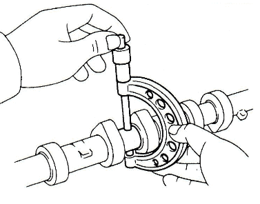
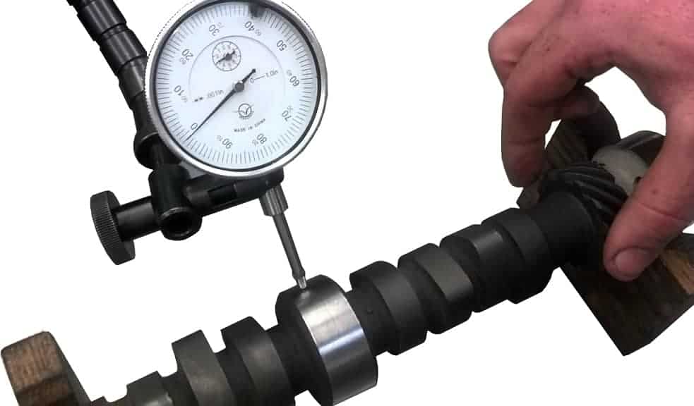
Camshaft Deflection Measurement:
The deflection of the camshaft should be measured at the middle bearing section using a dial gauge. When measuring with the dial gauge, we mount the gauge in a stand and place the camshaft in holders where it can be rotated. The pin of the dial gauge touches the back of the dial indicator; we set a preload of at least 2 mm here. As the camshaft is rotated, one can determine from the movement of the needle (from setting the preload to the maximum value at the cam height) whether the camshaft is bent.
The deflection must be less than 0.02 mm for certain engines. The maximum allowable is 0.1 mm. If 0.1 mm is exceeded, the camshaft must be replaced. Always consult the factory specifications.
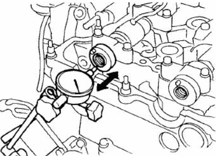
Axial Bearing Clearance Measurement:
With a dial gauge, we can measure the axial bearing clearance. Of course, the camshaft bearing caps must be tightened to the specified torque.
In this example, the axial clearance of the camshaft may range from 0.090 to 0.150 mm. If we measure a clearance of 0.120 mm, this is acceptable.
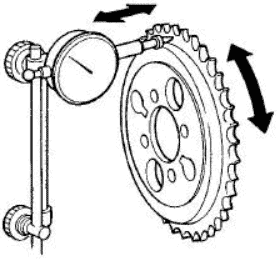
Runout of Camshaft Sprocket Measurement:
An engine with a timing chain has a timing sprocket. If a defect, damage, or assembly error causes runout in the sprocket, the timing chain will follow this motion every rotation, leading to increased wear or even breakage.
Again, with a dial gauge and stand, the runout of the sprocket can be measured. The needle of the dial gauge presses against the sprocket with a preload, causing the needle to follow every movement.
In this example, the sprocket must not exceed a runout of 0.25 mm.