Breakout box:
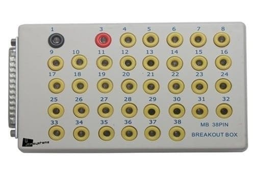
A breakout box is a tool used to perform measurements. With the help of a breakout box, you don’t need to open connectors or strip wires to perform measurements. Each wire has its own test point. The image below shows an example of a breakout box.
When voltages need to be measured on the control unit, this can only be done when the connector is connected. With a disconnected connector, neither accurate measurements can be carried out, nor will the engine be able to run if it deals with the engine control unit. For this reason, unfortunately, sometimes wires are pierced. By piercing the wire with the test probe, the voltage on that wire can be measured. However, the insulation is damaged, leading to new faults months or even years later due to a high resistance or cable breakage; moisture can easily enter the cable. A breakout box can prevent this. Reputable garages and well-trained specialists will therefore never pierce wires but will use a breakout box instead.
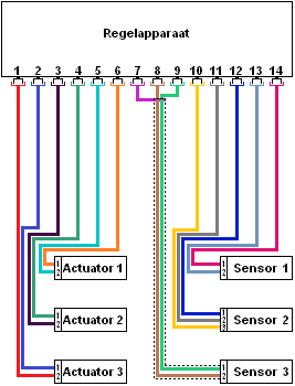
The diagram on the right shows a control unit connected to various sensors and actuators. There is still no breakout box in this situation, but a properly functioning engine management system.
The actuators (left) and sensors (right) have two or more wires per connector. These connections are often:
- plus (12 or 5 volts);
- ground;
- signal or control.
To conduct measurements on sensors and actuators, it can be checked whether there is enough space in the component’s sensor to insert the multimeter or oscilloscope probes. Often, the connectors are waterproof, and you cannot access the contacts without damaging the cable. Stripping the wire or piercing it is obviously not wise! To still perform accurate measurements, a breakout box can be placed between the control unit and the sensors/actuators. This is shown in the diagram below.
The connector of the control unit in the diagram on the right is placed on the breakout box. The connector of the breakout box, in turn, is connected to the control unit. In this way, the sensors and actuators are still connected to the control unit, so the entire system will function without faults. In the breakout box, connections between wires are made.
The breakout box contains all connection points; in the image below, these connections are displayed as circles above the numbers. The numbers of these connections correspond with the pin numbers of the control unit. So, each wire in the control unit’s connector has its own test point in the breakout box. Between the wires and the connection points, resistors are visible. These resistors often measure around 500 Ohms and serve to protect the measurement, which might be incorrectly carried out. Without these resistors, the likelihood of the control unit being blown is considerably greater.
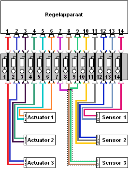
Example of a measurement: When the signal of sensor 1 needs to be measured, the interest is in the voltages on pin numbers 1 and 2 of the sensor’s connector (these numbers are written small near the wires).
On pin 1, the pink wire is connected, and on pin 2, the blue wire is connected. When the connector is insulated, the voltage should be measured further up, namely at the control unit or the breakout box. The pink and blue wires go to pin 13 and 14 of the breakout box. The voltages measured on pin 13 and 14 are therefore the same as if measured directly on the control unit’s connector, or directly on the sensor’s connector.
In the above example, a long breakout box with 20 connections is shown. In reality, breakout boxes are often square or rectangular, and sometimes there are more than 100 connections available. Multiple connectors can also often be connected to a breakout box. In that case, pay attention to the coding. If the coolant temperature sensor, for example, needs to be measured, it must first be determined which control unit and thus which connector this sensor is connected to (e.g., T60). On the breakout box, other codes like T45 and T32 are also indicated; these are other connectors. The correct connector can be found in the wiring diagram.
Reading electronic diagrams:
To clarify the story below with the measurements, all terms, designations, and abbreviations of the respective electrical diagram are explained. The diagram below is of the “waterfall” type, meaning the plus(es) come from above and the ground is located at the bottom. The current essentially flows from top to bottom. Terminal 30 is the constant plus, terminal 15 is the switched plus. A supply voltage is present when the car’s ignition is on. Terminal 31 is the ground of the battery.
The diagram below is part of the fuel system with a fuel pressure sensor and the fuel lift pump with the float element:
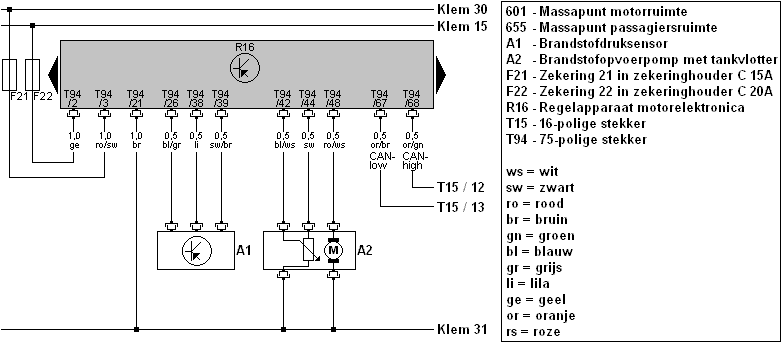
Fuses F21 and F22 are located in fuse holder C. This fuse holder is in the dashboard, on the driver’s side. The control unit (called R16) is the engine control unit. It is located behind the engine compartment, at the level of the windshield wiper mechanism. In the diagram, there are two black arrows on the left and right of the control unit, indicating that the control unit is larger than depicted. It is also shown that the pin numbers do not follow a logical order; starting from pin 2 and 3, then following 26, 38, and 39. On the control unit’s connector, the pin numbers do sequentially increase, starting from pin 1 up to pin 75. On these connections of the control unit, all wires to and from the sensors and actuators are connected.
Each wire has its own pin number and color. The explanation of the colors can be found in the legend. The wire ro/sw means it is a red wire with a black line (not the other way around).
Furthermore, components like the sensor and pump are marked with a code (A1 and A2). At A2, two wires run to the ground; one from the variable resistor of the tank float and one from the pump’s electric motor.
On the right side of the diagram, the CAN-bus wires can also be seen with the CAN-high and CAN-low. These wires run to connector T15, connections 12 and 13. Connector T15 is located elsewhere in the car; this location can be found in the workshop documentation. In this case, it concerns the connector on the Gateway. This diagram is used in the following examples, where measurements are conducted with the multimeter and the oscilloscope.
See also the page: Reading electrical diagrams.
Measuring with the multimeter on the breakout box:
The diagram is shown again below. In this case, we want to check the supply voltage. The diagram shows that on connector T94 of the engine control unit R16, pin 3 connects to the constant plus of the battery:
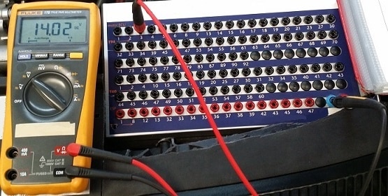
The image below shows a measurement being performed on the breakout box with the multimeter. The positive probe (the red one) of the multimeter is connected to connection 3 of connector T94 (T94 is shown in orange). The ground is measured via the blue connection; this is the central ground of the breakout box itself.
The diagram shows that the control unit is grounded through the wire and pin 21. When the negative probe is held on pin 21 and the voltage shows 0 volts, while the multimeter indicates 14.02 volts through the central ground, it might be that the ground wire between pin 21 and the ground point on the chassis is broken. This could explain when a fault code is stored about an interruption in the ground, or when the control unit cannot be switched on.
Measuring with the oscilloscope on the breakout box:
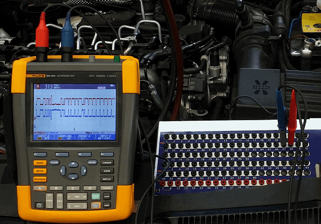
The oscilloscope can measure voltage over time. This can be handy for measuring CAN-bus signals. We will perform this below. The diagram shows that the CAN-bus wires are on pin 67 and pin 68 of connector T94 on the control unit R16:
The two probes of the oscilloscope are therefore connected to pin numbers 67 and 68 of the breakout box. The grounds of these probes are connected to any ground point of the car. Once the scope is correctly set up, the following image is visible:
With the help of these examples, one can get a clear picture of how the breakout box can be applied in practice. Voltages can be measured with both the multimeter and the oscilloscope. The downside is that currents cannot be measured.