Introduction:
Every automotive technician, from assistant to technical specialist, deals with electronics. Besides the electronics of comfort and safety systems found in lighting, windshield wiper motors, and ABS systems, we also find electronics in engine management systems and in the form of communication networks (e.g., CAN bus). Additionally, more and more vehicles are equipped with an electric drive train. Anyone wanting to understand electronics must start with the basics. In this section, we start with a brief explanation of the electrons circling an atom and will quickly proceed to electrical diagrams where the basic concepts of vehicle electronics are practically explained.
Atomic Nucleus with Electrons:
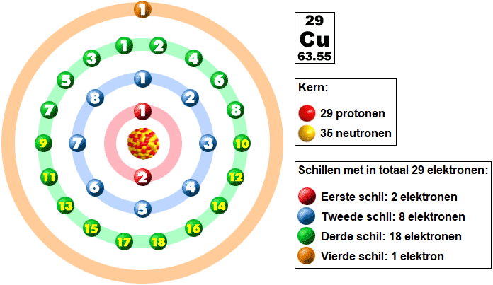
According to Bohr’s atomic model, an atom consists of a nucleus containing protons and neutrons, with electrons circling around it in multiple shells. The copper atom contains 29 protons and 35 neutrons in its nucleus.
The electrons are located in four shells. The distribution of electrons over these shells is called the electron configuration. Each shell has a maximum number of electron positions. The first shell (K) can hold two electrons, the second shell (L) holds eight, the third shell (M) holds eighteen, and the remaining shells hold 32 electrons.
The electrons in the innermost three shells are bound electrons. The electrons in the outermost shell participate in chemical bonds and reactions and are also referred to as “valence electrons.” The copper atom contains one valence electron. These electrons can move freely and shift to another atom. In the case of copper wire, the outer shells overlap, and the single electron can move across the shell of a neighboring atom.
The transfer of the valence electron is important for this topic. The jumping of electrons from one atom to another enables the material to conduct. Materials like copper, gold, and aluminum have a valence electron in the outer shell. Conversely, insulators like plastic, glass, and air do not have a valence electron. Therefore, this material is not conductive.
Electron Flow:
In the following image, we see a battery, a lamp, the conductor (copper wire), and a switch. Depending on the position of the switch, current either flows or does not flow through the circuit. The light blue rectangle represents the copper conductor with copper atoms (yellow) and jumping valence electrons (green).
- Switch opened: the electrons circle around the copper atom, but there is no electron flow through the consumer (the lamp). The lamp does not light;
- Switch closed: due to the battery creating a voltage difference, an electron flow is created from negative to positive. The current flows through the lamp and causes it to light due to the electron flow and the voltage difference.
The current moves from – (negative) to + (positive). This is the actual current direction. Previously, it was believed that the current moved from positive to negative, but this is not correct. However, for convenience, we adhere to this theory and call it the “technical current direction.” From now on, we will maintain this technical current direction, assuming that the current flows from positive to negative.
Current, Voltage, and Resistance:
In this section, we focus on the three concepts: current, voltage, and resistance. These concepts are commonly encountered in automotive technology. Current, voltage, and resistance each have their own magnitude, unit, and symbol.
- I = Current = Ampere (A)
- U = Voltage = Volt (V)
- R = Resistance = Ohm (Ω)
Current: In the previous section, we saw the electron flow through a circuit. The amount of electrons passing through a specific cross-sectional area of an electrical conductor per second is called the current. The unit of current is ampere (A). A current of 1 A is reached when 6.24 quintillion (6,240,000,000,000,000,000) electrons pass through a cross-section in one second. The more electrons flow in a given period of time, the higher the current is.
To understand how much current is required by electrical consumers in automotive technology, here is a list where current strength is estimated at a charging voltage of 14 volts:
- Starter motor gasoline engine: 40 – 80 A;
- Starter motor diesel engine: 100 – 300 A;
- Ignition coil: 3 to 6 A, depending on type;
- Fuel injector gasoline engine: 4 – 6 A;
- Electric fuel pump: 4 – 12 A, depending on pressure and flow;
- Electric cooling fan: 10 – 50 A;
- H7-lamp (halogen dipped beam) of 55 Watts: 3.9 A;
- Xenon lamp of 35 Watts: 2.5 A;
- LED lamps (PWM controlled and not via a ballast resistor): 0.6 – 1 A;
- Rear window defroster: 10 – 15 A;
- Seat heating: 3 – 5 A per seat;
- Standard car radio without onboard computer: ~5 A;
- Wiper motor: 2 – 5 A, depending on force;
- Interior fan motor: 2 – 30 A, depending on speed;
- Electric power steering: 2 – 40 A, depending on force.
Voltage: The voltage is the force that causes electrons to move. Voltage is a measurement of the difference in force between electrons at two points. The voltage is measured in volts, abbreviated as V. In automotive technology, we work with a “nominal voltage” of 12 volts. This means that the battery and all electrical consumers are based on 12 volts. However, in practice, we see that the voltage is never exactly 12 volts but always slightly lower, but more often slightly higher. Additionally, the voltage in electric drives is much higher. The consumers in a car consume voltage. For example, the rear window defroster uses about 10 amperes at a voltage of 14 volts. The current is not consumed and returns to the battery. The 14-volt voltage is used by the rear window defroster to generate heat. At the endpoint (the ground side), there is 0 volts left.
To understand possible voltage levels in a passenger car, here is a brief list of voltages we may encounter:
- Battery voltage: 11 – 14.8 v (nearly discharged to maximum alternator charging voltage);
- Piezo injector opening voltage: short-term 60 – 200 volts;
- System voltage of an electric drive vehicle (hybrid or BEV): 200 – 800 volts.
Resistance: Every electrical component has internal resistance. This resistance value determines how much current will flow. The higher the resistance, the lower the current. Resistance is represented by the letter R and the unit Ohm. We use the omega symbol from the Greek alphabet: Ω. In an electrical circuit, we can add an extra resistance to limit the current.
When a short circuit occurs, for example, if a positive wire touches the body, there is a very low resistance. The current quickly rises until a fuse blows to prevent damage. The following list shows the resistance of components commonly found in automotive technology:
- Copper wire 2 meters long and 1.25 mm² cross-section: 0.028 Ω;
- Lamp (21 Watt incandescent bulb): 1.25 Ω;
- Fuel injector for gasoline engine (high-ohmic variant): 16 Ω;
- Relay control circuit: ~ 60 Ω;
- Relay power circuit: < 0.1 Ω.
The resistance of a component often depends on the temperature: for example, the resistance of the bulb while burning is much higher than during the measurement when it was cold, where the current decreases as it gets warmer.
Summary: the resistance of an electrical component determines how much current will flow. Low resistance means that a lot of current will flow. The supplied voltage (often around 12 volts) is consumed in the electrical component, leaving 0 volts on the ground side. Current is not consumed, so it is the same on the positive side as on the ground side.
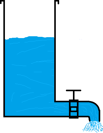
To better understand these concepts, it is sometimes helpful to reference the water tank example. The tank is filled with water and closed at the bottom with a faucet. The voltage and the flow of water through the faucet, which lets a certain amount of water pass, provides a good illustration of what happens with electricity in a consumer with internal resistance.
Voltage:
When the tank is filled with water, the water pressure at the faucet increases. The water pressure can be compared to the concept of voltage in electricity. The system must be closed; otherwise, the water drains away, and there is no more water pressure.
Current:
When we open the faucet, water flows through the faucet. The water flow is comparable to the concept of current in electricity.
Resistance:
The faucet regulates the resistance against the passage of water flow. As the faucet is opened wider, the resistance decreases, and the flow increases.
The same applies to electricity. With more resistance in the electrical circuit, there is less current and vice versa. Resistance does not affect the voltage.