Introduction auxiliary brake – parking brake:
The auxiliary brake / parking brake lever allows for modulated braking on the rear brakes and activates the parking position. This part falls under the “air-consuming” section, where the components in the image below are indicated in green.
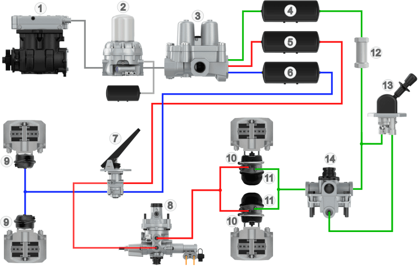
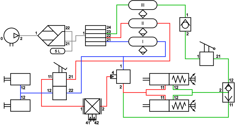
Legend auxiliary brake / parking brake:
1 to 6: Air supply
12: Check valve
13: Parking brake valve
14: Relay valve
- Blue: air supply
- Yellow: air-consuming
- Green: parking brake / emergency brake
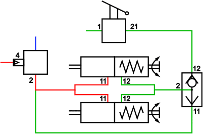
In the four-circuit protection valve (3), the brake circuits are separated from one another. In the image above, the brake circuits are indicated with colors:
- circuit 1 (red) is the rear wheel brake circuit;
- circuit 2 (blue) is the front wheel brake circuit;
- circuit 3 (green) is the auxiliary brake or parking brake circuit;
- circuit 4 is the trailer or semi-trailer brake circuit (not shown).
The auxiliary and parking brakes are separated from the other air-consuming circuits in the four-circuit protection valve. Air tank 4 serves as air storage.
From the air tank, air flows through the check valve (12), which only allows air to flow in one direction. Airflow in the opposite direction is blocked. The check valve is connected to the input of the parking brake valve (13).
The driver operates the handle of the parking brake valve. The handle is usually placed on the dashboard or next to the driver’s seat. With the movement of this handle, braking can be applied, and when it reaches the end stop (for parking), all air is expelled from the spring brake chambers (11), locking the brakes. The parking brake valve controls the relay valve (14), which, depending on the amount of air supplied by the parking brake valve, allows the air pressure from the check valve to pass through to the spring brake chambers (11). In addition to the relay valve, a double check valve (also called two-way valve) may also be present. This valve is explained in the “double check valve” paragraph, so it is not included in this diagram yet.
Check valve:
Without air pressure, the spring brake chambers remain in the rest position, causing the brake linings to press against the brake disc or drum. Air pressure is required to actuate the spring brake chambers and release the truck brakes. If a leak occurs in one of the other brake circuits and pressure in circuit 3 drops, there is a risk of the rear brakes dragging.
The check valve prevents air from flowing back to the tank. In the flow direction (from 1 to 2), the ball is pushed off its seat by air pressure, but in the opposite direction (from 2 to 1), the ball blocks the airflow.
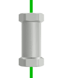
In older trucks, the check valve was often a separate component, but in newer trucks, it is often built into another component, such as the four-circuit protection valve or the parking brake valve.
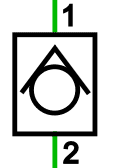
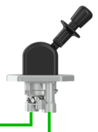
Parking brake valve:
With the parking brake valve (also called emergency brake or handbrake valve), the driver can vent and supply air to the spring brake chambers of the rear brakes.
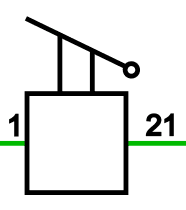
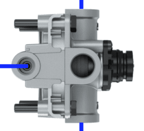
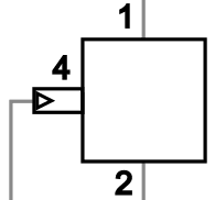
The following two images show a drawing of the parking brake lever on the valve, along with its symbol. The codes indicate the input and output of the valve: 1 is input and 21 is output 1. An output 2 may also be present and is labeled as 22.
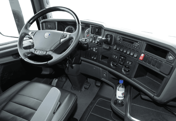
In the following image, we see the dashboard of a Scania R730 (2010) with the parking brake lever next to the steering wheel, located in the dashboard.
- Vented: without air pressure, the brakes are locked (parking position);
- Pressurized: the rear brakes are released (driving position);
- Partially pressurized: while moving the lever toward the parking position, the pressure in the spring brake chambers drops and braking occurs. The further the lever is moved toward this position, the harder the braking force.
Currently, it is set to the parking brake. To release the parking brake, the lever must be pulled toward you to tilt it upward.
When the lever is in the upward position, the spring brake chambers are pressurized and driving is possible.
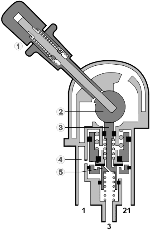
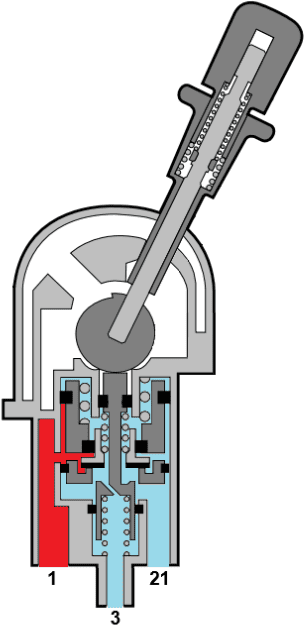
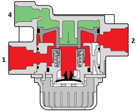
In the next image, we see the mechanism inside the parking brake valve along with the legend.
The driver operates the handle (1) by pulling the release button outward against spring force. This releases the lock so the lever—and thus the eccentric (2)—can be rotated on its axis.
The eccentric has an off-center shaft, so during rotation of the handle, the push rod (3) is pressed downward against spring force.
The sealing valve (4) and the lower end of the push rod (5) block or allow airflow in the various positions. In the position shown, sealing valve 4 blocks the passage of air between the input (code 1) and output (21). When the truck is parked, air escapes from connection 21 through the vent port (code 3) to the outside air.
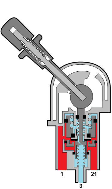
The images below show the airflow in the “driving” and “park” positions.
Legend:
1. Handle with spring
2. Eccentric
3. Push rod
4. Sealing valve
5. Lower end of push rod
- Driving position: input 1 and 21 are interconnected, so the air supply from the air tank reaches the spring brake chambers. The spring brake chambers are pressurized and the brakes are released;
- Park position: the air to the spring brake chambers is vented via port 3 and supply via port 1 is closed off. The spring brake chambers are vented so that the brake shoes press against the disc or drum.
Relay valve:
A relay valve is mainly used to allow a fast response time (pressurizing and venting) of the brake chambers at a great distance. A long, thin air line runs from the cabin to the rear axle to control the relay valve. The air pressure from the tanks is already present there and can be passed or blocked by the control line. The operation of the relay valve is comparable to a relay in electronics: with a small pilot current, a large main current can be switched on and off. However, unlike an electric relay, the control pressure determines the amount of airflow from the tank to the brake chamber.
A relay valve can be found in several locations within the air brake system:
– between the ALR and the diaphragm chambers of the rear brakes;
– between the parking brake valve and the spring brake chambers of the rear brakes.
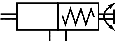
The relay valve has the following connections:
- 1 and 2: input and output
- 4: control.
The air pressure at port 4 (control) determines the output pressure at port 2. The higher the control pressure, the higher the output pressure.
The images below show the relay valve in de-energized and energized states. The amount of control pressure determines the position of the plunger that is pushed downward. The further the plunger is pushed down, the larger the opening between 1 and 2.
Legend:
1. input (supply air)
2. output
4. control
- Green: control pressure
- Red: pressure from tank
- Blue: atmospheric pressure
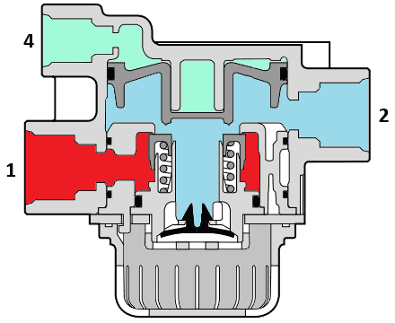
Double check valve:
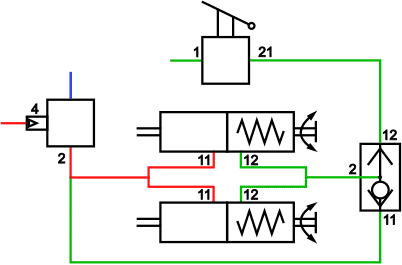
An air brake system can include a so-called double check valve (also known as a two-way valve). This valve is located between the input of the spring brake chambers (12) and the outputs of the parking brake valve (21) and relay valve (2). In the diagram below, this valve is shown in place of the relay valve.
The purpose of the double check valve is to prevent excessive force from acting on the brakes if the service brake and parking brake are applied simultaneously.
Driving position:
The parking brake is released and there is no braking. Connection 12 is supplied with full air pressure via the parking brake valve. The plunger in the valve is pushed downward so that port 11 is closed and there is a passage via output 2 to the spring brake chamber. The spring in the spring brake chamber is compressed, so the parking brake is disengaged.
When braking, the foot brake valve conducts air via the relay valve to the diaphragm chambers (11), activating the service brakes. The air from the foot brake valve is also present at port 11 of the double check valve. The pressure at port 11 is lower during partial braking than the pressure at 12, which keeps the plunger closing port 11.
Parking brake position:
When the truck is parked, the green lines in the image are unpressurized. The spring in the spring brake chamber pushes the brake linings against the brake drum or disc to keep the truck stationary. The plunger is in the central position.
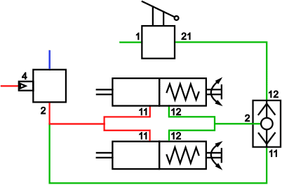
Parking brake and service brake applied:
The parking brake valve has vented port 12 of the double check valve. The spring in the spring brake chamber presses the linings firmly against the disc or drum.
If the driver applies the service brake while parked, the foot brake valve—via the relay valve—supplies port 11 of the double check valve. The plunger in the valve is pushed upward by the air pressure, closing port 12. Via port 2, the spring brake chambers are pressurized to push the spring back. This prevents excessive force on the brake system and avoids damage.
Combined diaphragm and spring brake chamber:
A diaphragm chamber is a type of brake chamber. The energy supplied by the air pressure is converted into movement inside the diaphragm chamber. With a lever, this movement is converted into a force that presses the brake lining against the brake disc or drum.
The force pressing the brake lining depends in part on the lever ratio and the air pressure in the diaphragm chamber. The diaphragm chamber is used in the service brake. The diaphragm chamber is not suitable for parking because, with the engine off and in the parking position (assuming the tanks are empty), there is no air pressure available to press the brake linings against the disc or drum. Therefore, trucks are equipped with a spring brake chamber for the parking brake, which is often combined with the diaphragm chamber for the service brake.
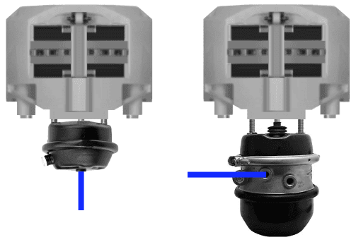
The image next to this shows two brake calipers, with two types of brake chambers below them:
- left: diaphragm chamber for the front axle.
- right: diaphragm chamber with the spring brake chamber below it for the rear axle.
The image below shows a combined diaphragm and spring brake chamber. Number 1 indicates the air ports used to pressurize and vent air chambers A (parking brake) and B (service brake).
- Left section: here are the components for the emergency brake and parking brake. The strong spring (3) pushes the diaphragm (2) and the red rod (6) to the right, causing the lever to move to the “parking” position. At rest, the spring presses the brake linings against the brake disc or drum via the mechanism;
- Right section: the diaphragm (4) and spring (5) are in the furthest right position when parked to allow the push rod to make the outward movement.
When parked, there is no air pressure in chambers A and B. Atmospheric pressure is present here.
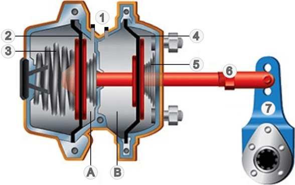
Legend:
1. Air ports for spring brake (left), diaphragm (right);
2. Parking brake diaphragm
3. Strong spring parking brake
4. Service brake diaphragm
5. Service brake spring
6. Push rod
7. Lever
A. Air chamber to release parking brake
B. Air chamber to operate service brake
Releasing the parking brake:
To release the parking brake, the driver moves the parking brake valve to the driving position. The parking brake valve supplies about 5.5 bar air pressure to the spring brake chamber. Air chamber A is filled.
In the image, air chamber A is colored light blue. Since the parking brake spring is compressed, the service brake spring pushes the push rod to the left. The lever rotates in the direction that releases the brake linings from the disc or drum.
In this position, the spring brake chamber is pressurized, the brake is released, and the wheel can turn.
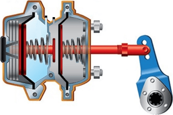
Operating the service brake:
While driving, the spring brake chamber remains pressurized. To modulate braking, the driver operates the foot brake valve, which lets air into the right chamber. This pushes the diaphragm to the right against spring force, while at the same time the push rod also moves to the right. In this position, as shown, maximum braking is applied.
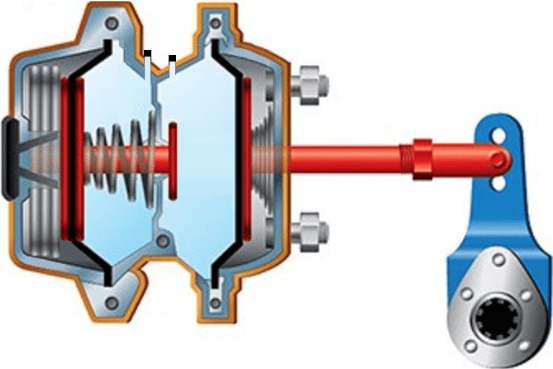
Operating the parking brake:
The driver operates the parking brake lever to return the spring brake chamber to the parking position. When the truck is stationary, the lever can be placed in this position in one smooth movement. In the event of a failure in the service brake, the driver can gradually move the parking brake lever while driving to apply more or less pressure to the spring brake chamber.
When the parking brake lever is moved to the “park” position, this releases the air pressure from the left air chamber. The spring pushes the push rod fully to the right, pressing the brake linings firmly against the discs or drums.

Without air pressure, the parking brake cannot be released in principle. To allow the wheel to roll anyway, a spindle is located at the rear of the spring brake chamber. With a tool (ratchet and socket), the spindle can be rotated to manually relax the spring.
Related page: