Introduction:
When the engine is running, the alternator ensures the battery is charged and the consumers are powered (such as the radio, lighting, etc.). The alternator is driven by the serpentine belt. The serpentine belt drives the alternator pulley, which is connected to an internal shaft. The kinetic energy is converted into electrical energy (and heat) within the alternator.
The engine speed affects the alternator voltage. The faster the engine runs, the faster the pulley spins, generating more current. The voltage should not be too high, so it is limited by the voltage regulator.
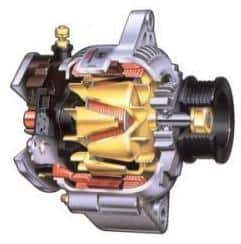
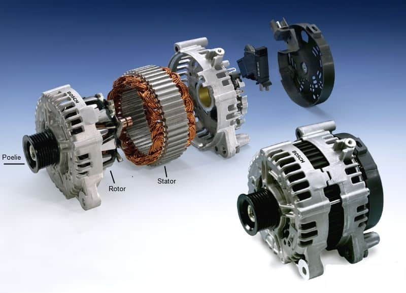
The adjacent image shows an exploded view of an alternator. The pulley is mounted in the housing with a bearing. The rotor shaft is attached to the pulley, which rotates when the pulley is driven by the serpentine belt. The stator is mounted between the two parts of the housing, where the rotor spins. Often, a plastic cover is found on the rear of the alternator, hiding the voltage regulator and the alternator connections.
Alternators generate alternating current (AC), but the vehicle’s electrical system operates on direct current (DC), as does the battery. The AC is converted to DC using the diodes in the diode bridge. The voltage generated depends on:
- The speed at which the conductor and magnetic field move relative to each other
- The length of the windings
- The strength of the magnetic field
Multiple connection codes are marked on the alternator housing (rear) to indicate their functions:
- B+ a goes to the battery; the charging voltage and charging current pass through here.
- D+ is the excitation voltage for adjusting the alternator voltage.
- D- is the ground for the alternator.
- W a was historically used for tachometers in old diesel engines. It is now obsolete.
- DF or LIN a are potential connections for rotor excitation from the engine management system.
Operation:
Electricity is generated as the rotor spins within the stator. The rotor is an electromagnet, only becoming magnetic when current flows through it. Thus, the alternator needs help from the battery before it can begin charging. The residual magnetism in the alternator is insufficient to allow electric current through the diodes.
Electric current to magnetize the rotor flows from the battery through the ignition switch and charge indicator light to the D+ terminal of the alternator, then to the rotor. From the rotor, the current flows through the regulator to the ground. When the ignition is turned on, the charge indicator light illuminates, and the rotor is magnetized simultaneously. Once the alternator begins charging, the charge indicator light goes out.
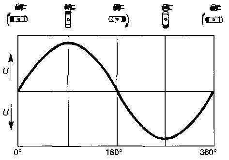
As the alternator charges, the rotor’s north and south poles move relative to the stator, generating AC in the stator. The generated voltage in one rotation of the magnet in the conductor takes the form of a sinusoidal wave, as shown in the image.
Since this is AC and vehicle consumers only operate on DC, it needs rectification. Diodes convert the AC to DC.
Charging voltage and current must be regulated as well; when the engine runs at high speed with few consumers on, the alternator needs to charge minimally. As more consumers are switched on, the alternator must deliver more charging current, which can rise to 75 to 120 Amps under full load (depending on the vehicle type). How it all works is described in the sections below.
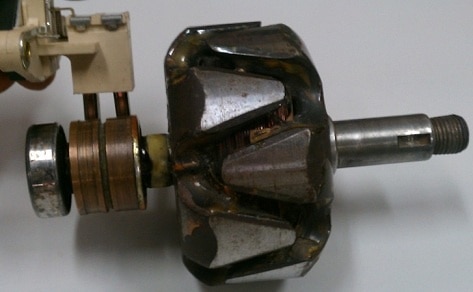
Rotor:
The rotor is not a permanent magnet but an electromagnet. It becomes magnetic by passing a current through it, generating AC. The generated voltage can be controlled by increasing or decreasing the rotor current, which is the task of the voltage regulator.
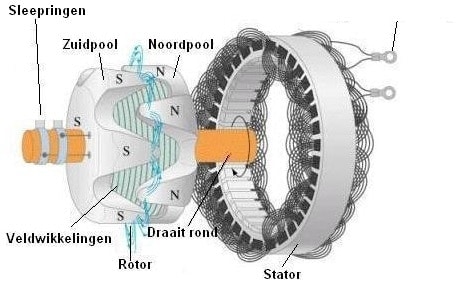
The rotor has claw poles (north and south poles). Each claw-pole half usually consists of 6 or 7 poles, and the other half has the same number, resulting in 6 or 7 north and south poles or 12 or 14 pole pairs. The number of pole pairs affects the voltage generated in the stator.
The magnetic field in the alternator is established when the rotor is energized, which happens when the car’s ignition is turned on. To energize the rotor, a field current is passed through the field windings, sourced from the battery and transferred via the slip rings and brushes to the field windings. This current flows from the north pole to the south pole because one slip ring is connected to the north pole and the other to the south pole.
When the rotor is removed, it can be tested for defects. The rotor resistance is often around 3 Ohms. Consult the factory data for the exact value.
Stator:
The alternator used in nearly all vehicles is a three-phase alternator. This means it is composed of three stator coils connected to a single stator core and a rotor. Each stator coil produces its own induced AC. Since the coils are mounted 120 degrees apart, the generated voltages are also 120 degrees out of phase. These voltages are rectified by six diodes: three negative and three positive diodes.
The stator core consists of laminated sheets separated by insulation material. The stator core enhances the magnetic field and increases generated voltage. The stator coils may be connected in a delta configuration (recognized by 3 d2 connections) or a star connection (4 connections, 3 loose, and 1 connection where the 3 coil ends are linked). The star connection is common for faster high voltage attainment, whereas delta configurations apply where higher power output is needed.
If a stator coil contacts the core (short circuit) or if one coil is broken (open circuit), the stator will malfunction. A multimeter can check for short or open circuits, provided the stator coils are disconnected; both ends must not contact other parts. Unsoldering is often sufficient. Coil resistance should be very low; about 0.05 Ohms. The resistance between the stator coils and stator core must be infinitely high. If resistance exists (even if very high), it indicates a connection.
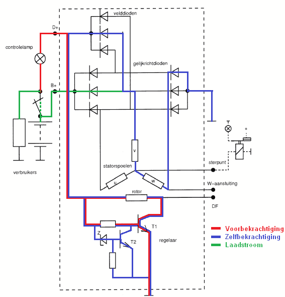
Excitation, self-excitation, and charging current:
Excitation:
The engine is off and the charge indicator light is on. The excitation current flows from the battery, through the ignition switch, rotor, and regulator, to the ground. This occurs as the zener diode in the voltage regulator cuts off and T1’s base current is activated as T2 stops conducting.
Self-excitation:
When the engine starts, the rotor is sufficiently magnetized to switch to self-excitation. The self-excitation current flows via the negative rectifier diodes, stator coil, field diodes to the rotor, and through the voltage regulator to ground.
Charging Current:
The stator coil generates AC as the rotor turns. The green line marks the path the current takes from stator coil V to the battery and consumers. The current is converted from AC to DC by a rectifier diode and passes through the B+ terminal to the battery and consumers.
The charging current flowing through the B+ terminal to the battery and consumers powers the vehicle’s entire electrical supply. When the engine is off, consumers draw power from the battery. When the engine runs, the alternator must supply sufficient current to power all consumers. Thus, no battery power is used when the engine runs. The alternator’s charging current depends on the number of engaged consumers and the battery’s charge state. The maximum charging current is usually marked on the alternator (typically between 60 and 90A).
The alternator’s charging voltage can be checked easily if functionality is in doubt. By measuring across the battery terminals with the engine running using a voltmeter (multimeter), the alternator’s output can be verified:
- If the voltage is around 14.2 volts, the alternator is working correctly;
- If the voltage is 13.8 volts, the battery is nearly full and consumers are switched off, requiring less from the alternator, which does not affect the charging voltage;
- If the voltage is 12.4 volts or lower, the alternator is not charging properly. This is equivalent to the voltage of a fully charged battery, indicating a problem with the alternator;
- If the voltage is lower than 12.4 volts, the alternator failed to charge, and the battery will deplete further until the voltage drops to 8 volts. The engine will then stall, and electrical functions will cease.
If the alternator fails to charge, replacing it is an option. Although expensive, it might be more economical to use a refurbished alternator. Many refurbishing companies dismantle and rebuild the alternator, saving over half the cost of a new one. Always disconnect the battery’s negative terminal before replacing the alternator! Failing to do so could cause sparks and short circuits if the B+ terminal contacts the chassis or engine block, damaging costly electronic components.
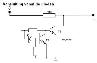
Voltage Regulator:
The voltage regulator switches the magnetic field on and off by controlling the rotor current. It maintains a constant charging voltage (between 13.2 and 14.6 volts). The charging voltage depends on the engine speed. As the crankshaft speed increases, so does the rotor speed. Without regulation, the voltage would rise to 30 volts at high speeds, but the voltage regulator prevents this. If the voltage exceeds the set limit, the zener diode (in the circuit) conducts, directing T1’s base to ground through T2. T1 cuts off, causing the magnetic field to collapse, reducing alternator voltage. The rotor current is thus interrupted, so the alternator ceases charging momentarily.
The constant cycling of T1 controls the voltage.
If the voltage at the D+ terminal is below the set regulation voltage, current flows from D+ through the rotor to the D- terminal (ground), causing the alternator to generate voltage. When the D+ voltage exceeds the regulation voltage, the zener diode conducts, turning on transistor T2, preventing transistor T1 from conducting, and halting current through the rotor. The magnetic field is disabled, and the charging voltage decreases. The voltage drops until the zener voltage ceases, allowing transistor T2 to cut off and transistor T1 to conduct again. This cycle repeats continually.
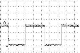
Below are two oscilloscope traces measured at the alternator’s DF terminal. These signals feed to the engine control module. The rotor is magnetic when connected to ground.
The signal in Chart 1 was taken with minimal or no consumers switched on. Hence, the rotor is minimally magnetized. The duty cycle here is about 10%.
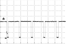
The signal in Chart 2 was taken with many consumers on. Here, the rotor is considerably more excited to reach the 14.4 volt charging current. The duty cycle here is about 50%.
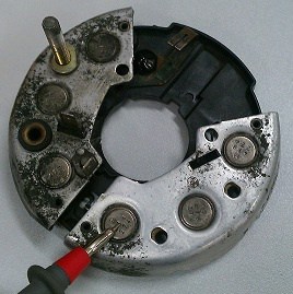
Rectifier Diodes:
The alternator supplies AC, but since only DC is used in the vehicle, the AC must be converted to DC. This is achieved using rectifier diodes. Diodes allow current to flow in one direction only. The positive part of the AC is utilized while the negative part is discarded.
The image shows a disassembled diode bridge. The red test lead indicates one of the three negative diodes. On the other side of the diode bridge are the positive diodes. The stud is the B+ terminal, with the thick cable connected to it leading to the battery.
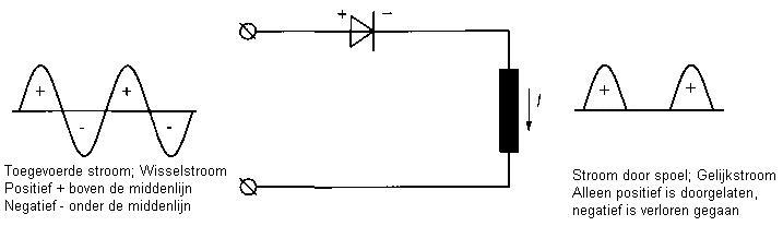
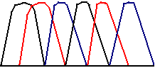
This is the principle of a single-phase alternator. In the image above (on the right), the phase is intermittent, with no voltage for a moment, followed by a new phase. Therefore, no voltage is generated in the interval between phases. In three-phase alternators, star and delta connections are used to achieve the result below.
The image below shows three different colors: black, red, and blue, representing separate phases. As seen, there is considerable space between the black phases. By connecting the other phases, this space is bridged, allowing a steady current flow.
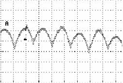
After rectifying the voltage using rectifier diodes, a small ripple remains, known as ripple voltage. This ripple should never exceed 500 mV to avoid faults or damage to vehicle electronics. The image shows an oscilloscope trace measured at the battery. This trace can change with engine speed or when consumers are turned on.
Overrunning Pulley:
Many modern alternators feature an overrunning pulley (see image below). These pulleys are driven in one direction only. By removing the serpentine belt from the pulley and manually rotating it, the alternator internals will turn in one direction and remain still in the other. This system protects the serpentine belt. When the engine is at high speed and the throttle is suddenly released, the engine speed drops rapidly. A heavy alternator decelerates more slowly. Consequently, the serpentine belt could be severely stressed and possibly severed, as it must now decelerate the alternator. An overrunning pulley helps the alternator rotate during acceleration but allows it to spin at its speed during deceleration.
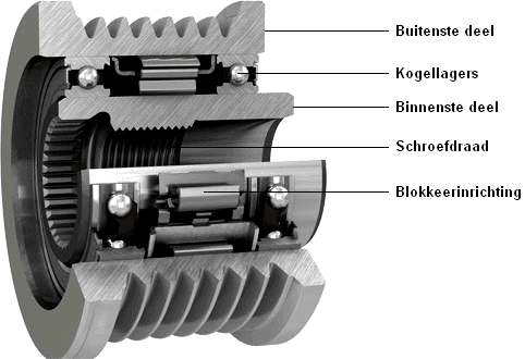
The pulley is threaded onto the rotor shaft (see image above). The outer pulley portion engages the inner portion in one rotation direction. The locking mechanism ensures that the inner part is clamped against the outer part. The entire pulley then locks so that the serpentine belt drives the alternator. Upon releasing the accelerator pedal, the inner part rotates faster than the outer part; the engine speed decreases faster than the rotor speed. The locking mechanism disengages, allowing the bearings to enable different rotor and crankshaft speeds.
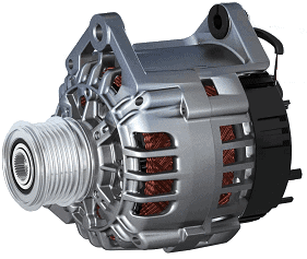
The image shows an alternator with an overrunning pulley.
Energy Recovery:
When the alternator is charging at maximum capacity (with many consumers engaged), increased fuel consumption occurs because the alternator requires more power to operate due to a stronger magnetic field in the stator. The magnetic field causes the rotor to drag more, necessitating additional effort from the crankshaft to turn the belt. Automakers have developed a solution; the alternator always charges but does not maximize its capacity during driving (unless the battery is depleted). Maximum charging occurs when engine braking. Therefore, when the driver releases the accelerator and allows the vehicle to coast (like approaching a traffic light or freeway exit), the vehicle uses no fuel, and the kinetic energy keeps it rolling. Now, the battery charges until throttle input resumes when the alternator maintains stable voltage. This charging method reduces fuel consumption.
Possible Alternator Defects:
Various typical issues or defects may occur in the alternator. Usually, the technician knows what to check or measure next. Below are some characteristic complaints:
- The charge indicator light functions normally during excitation but extinguishes only at higher engine speeds; likely a defective alternator (probably a faulty field diode).
- Similar complaint as above, but the light glows dimly at high engine speeds or with many consumers switched on; likely a defective alternator (probably a faulty diode).
- The charge indicator light glows weakly during excitation and extinguishes only at higher engine speeds; possibly a defect in the alternator or its wiring or connections.
- The charge indicator light does not illuminate during excitation or at operating conditions; defective alternator, poor wiring/connections, or a faulty charge indicator light.
Checking Charging Voltage and Current:
The energy output from the alternator depends on the capacity and demand of consumers and the battery. For example, the alternator must deliver 100A to power the consumers and charge an empty battery. When the battery is full and no consumers are engaged, alternator output drops near zero. The alternator’s maximum capacity is usually displayed on the type plate, often between 65A and 120A, for instance, 14V 17/85A (regulated voltage 14V, charging current of 17A at 1800 RPM and 85A at 6000 RPM).
A wiring or alternator defect may prevent reaching maximum capacity when loaded. This can be verified by measuring the charging current with a current clamp while fully loading the alternator, for example, by switching on as many consumers as possible. The measured value should match the specified alternator output.
The regulated voltage can be measured between the B+ terminal and ground at an engine speed of 2000 RPM. The voltage should range between 13.8 V and 14.5 V. To verify wiring, measure the voltage difference between the battery positive terminal and the alternator’s B+ terminal; it must be less than 0.4 V. Should the voltage be higher, a problem with the wire or connections exists. A poor ground circuit can affect the charging and other systems. This can be checked by running the engine at 2000 RPM and measuring the voltage between the battery’s negative terminal and the alternator housing; this voltage should also be less than 0.4 V.
Related page: