Introduction to Air Supply:
In the air supply system, air is drawn into the compressor and compressed to a desired pressure. The compressed air is then cleaned and dried in the air dryer, minimizing moisture delivery to the components in the brake system. The four-circuit protection valve distributes the air over multiple circuits and, if a leak occurs in one of these circuits, it protects the intact circuits from pressure loss.
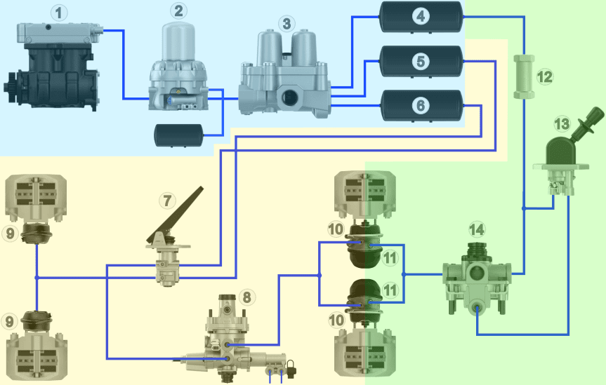
The image below shows several parts of the pneumatic brake system of a truck, with the components in the blue section belonging to the air supply section.
Legend:
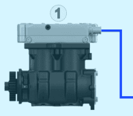
1. Air Compressor
2. Dryer with Wet Reservoir
3. Four-Circuit Protection Valve
4. Air Reservoir Circuit 3
5. Air Reservoir Circuit 1
6. Air Reservoir Circuit 2
7. Foot Brake Valve
8. Load-Sensitive Valve (ALR)
9. Front Diaphragm Cylinders
10. Rear Diaphragm Cylinders
11. Rear Spring Brake Cylinders
12. Check Valve
13. Parking Brake Valve
14. Relay Valve
- Blue: Air Supply
- Yellow: Air Consumption
- Green: Parking/Emergency Brake
This page discusses the blue-highlighted air supply section with the compressor, dryer, four-circuit protection valve, and air reservoirs.
Air Compressor:
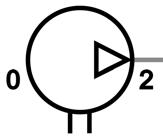
The air compressor for vehicles with pneumatic brakes is driven by a gear from the combustion engine. The incoming motion activates the crankshaft in the compressor. The connecting rod causes an up-and-down motion of the piston, drawing in atmospheric air during the downward stroke. The drawn air (connection 0) is compressed by the piston and then directed to the reservoirs via the pressure valve and connection 2.
The air compressor, mounted on the engine, consists of various components including the drive gear, oil seal, crankshaft, pistons, cylinders, intake valve, exhaust valve, and unloader valves. These components work together to draw in, compress, and store air in the air reservoirs.
The air compressor can have different designs, like single or multi-cylinder, and may be driven by the engine or electrically. Electric and hybrid vehicles commonly use an electrically driven air compressor. Maintenance of the air compressor often includes lubrication, using engine oil lubrication systems, and cooling, which can occur via the engine’s cooling system or a separate cooling circuit for electrically driven compressors.
To prevent the system pressure from getting too high, excess air pressure is vented through a pressure regulator and relief valve integrated into the air dryer housing. Once the desired pressure is reached, the compressor can be deactivated to save fuel. Unloader valves ensure the compressor does not build up pressure when the desired pressure is reached.
In situations where the pressure may become dangerously high, a safety valve is employed to relieve the pressure. A two-stage compressor can further reduce fuel consumption by building pressure in two phases, enhancing the compressor’s efficiency.
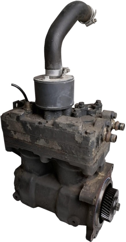
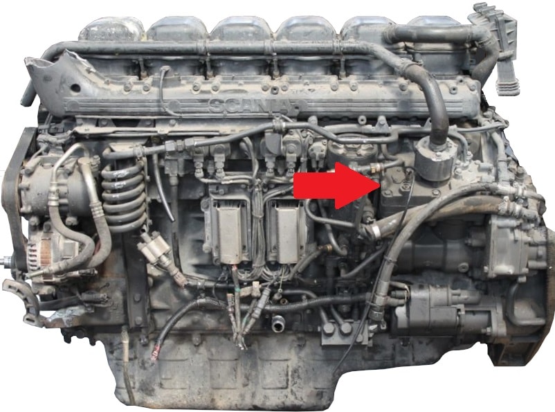
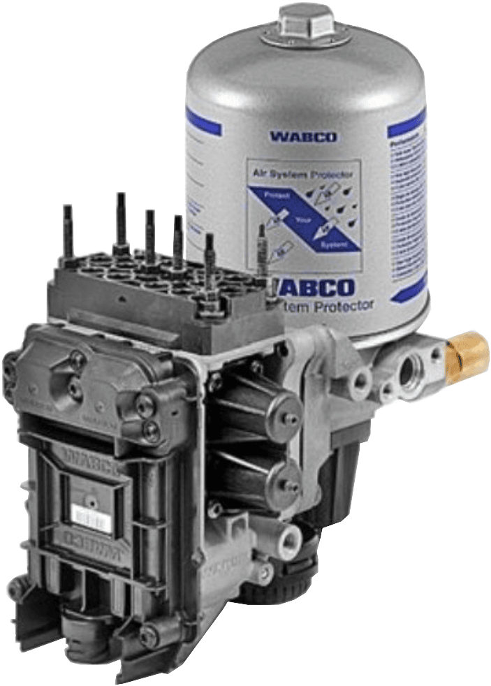
The images below show the air compressor and installation position on a Scania DC12.
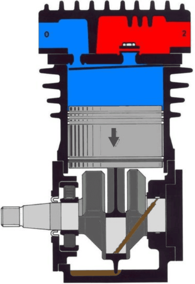
The crankshaft in the air compressor is driven by a gear transmission. When the engine is running, the piston in the compressor moves up and down. During the downward stroke, a vacuum is created in the cylinder space (blue), causing the intake valve to open and air to flow into the cylinder space. The vacuum in the cylinder space ensures that the exhaust valve remains closed.
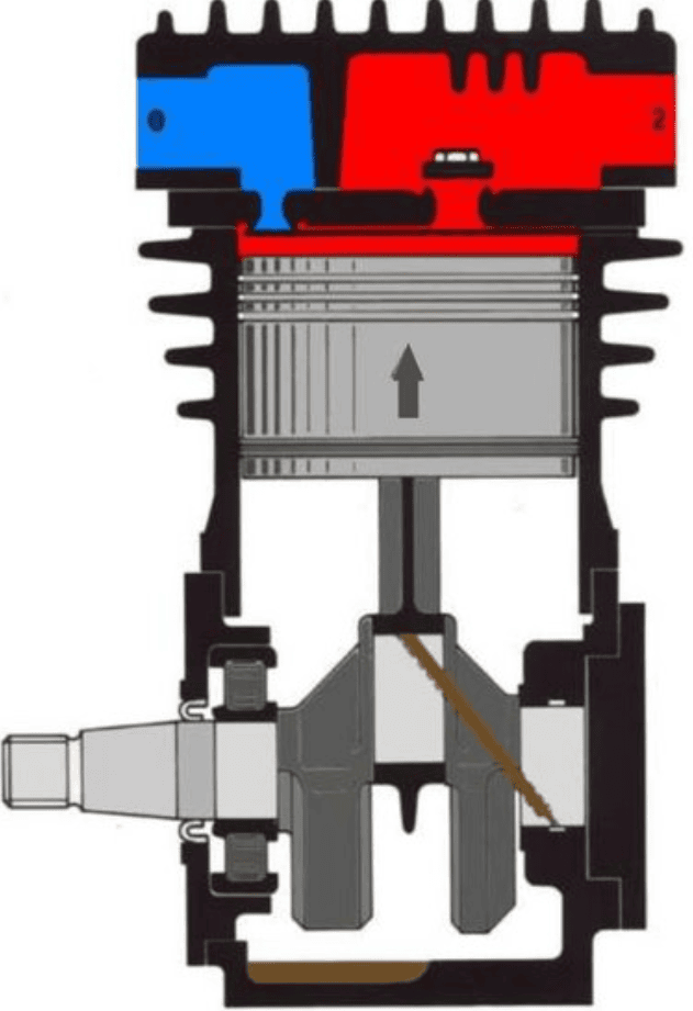
As the piston moves upward, the air is compressed (red), creating overpressure in the cylinder space, which closes the intake valve and opens the exhaust valve. The air is pressed past the exhaust valve into the air reservoirs.
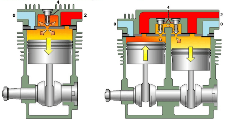
The truck air compressor can be equipped with two cylinders. The crank journals are rotated 180 degrees apart, so the direction of motion is opposite. The images below show a compressor with one cylinder (left) and two cylinders (right).
Air Dryer:
The air supplied by the compressor contains moisture (water vapor). When this water vapor condenses, water forms, which can cause corrosion in components such as air reservoirs, valves, brake cylinders, and lines, especially during freezing. Additionally, oil particles from the air compressor and dust particles from the drawn air can enter the compressed air. To prevent this, an air dryer is necessary to filter out moisture, oil, and dust particles from the air.
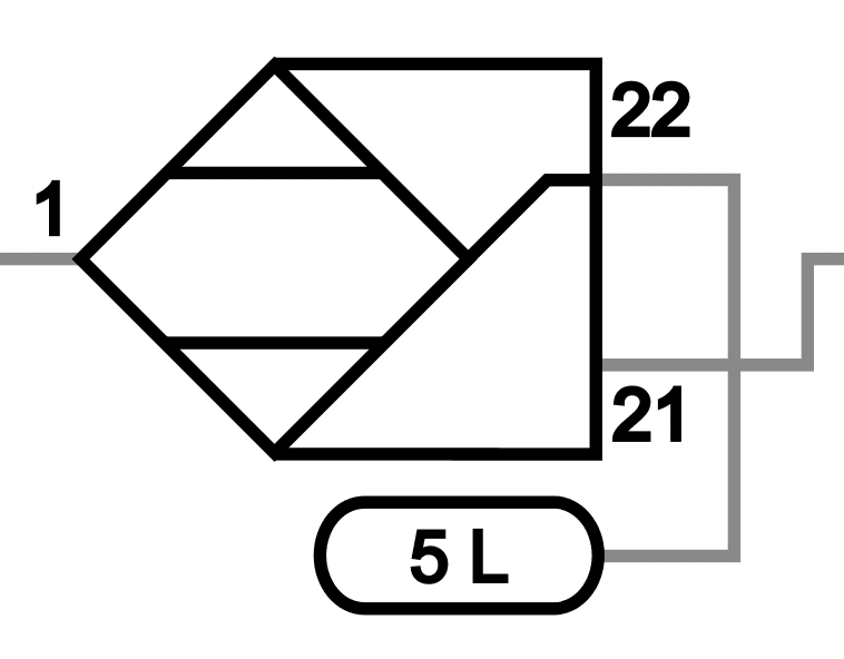
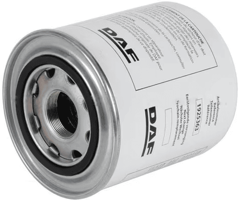
The following image shows the air dryer (with the blue background, from the overview of the air supply section) alongside the symbol with codes.
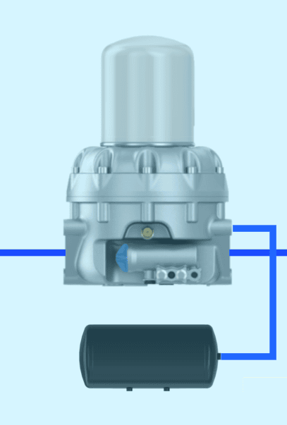
A pressure regulator is often integrated into the air dryer. Once the maximum system pressure is reached, air is vented through the relief valve, also expelling the absorbed water from the dryer.
The air dryer is typically mounted on the vehicle’s chassis, between the expansion/cooling line and the four-circuit protection valve.
The air dryer consists of various parts: the dryer housing, drying cartridge, inlet, outlet, and heating element. Some air dryers have a different type of cartridge where the dryer housing and drying cartridge are combined.
The operation of the air dryer involves passing compressed air through a filter where dust and other debris remain, while moisture and oil particles are directed to a chamber with pellets (drying cartridge) to be absorbed. The granules in this cartridge are hygroscopic, meaning they readily attract moisture. The air is guided through various spaces in the air dryer, where the moisture is removed by the granules. The drying cartridge has a limited capacity to absorb moisture. Therefore, the saturated drying cartridge must be regularly replaced or regenerated.
During regeneration, a small amount of air flows in the opposite direction through the drying cartridge to absorb moisture, after which the moist air is expelled and the accumulated water is discharged from the air dryer housing. Despite regular regeneration of the granules, the drying capacity gradually decreases due to saturation with oil mist and dirt, requiring periodic replacement of the drying cartridge according to the manufacturer’s recommendations.
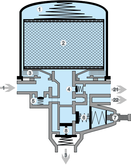
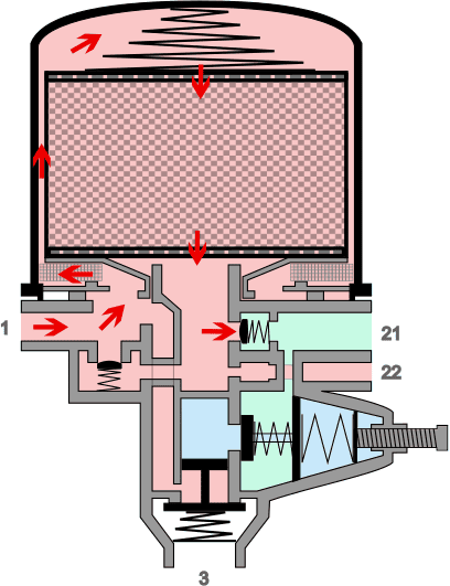
The image below shows a cross-section of an air dryer with internal pressure regulation. The situations in which the pressure is built up, regulated, and the filter element regenrated are described beneath the image.
Legend:
1. Air Dryer Element
2. Drying Element with Pellets/Granulate
3. Coarse Filter
4. Check Valve
5. Bypass Valve
6. Pressure Control Valve
7. Adjustment of Pressure Control Valve
8. Relief Valve
-> 1. Inlet Air Dryer from Compressor
-> 21. Outlet 1 to Four-Circuit Protection Valve
-> 22. Outlet 2 to Wet Air Reservoir
-> 3. Venting/Relief Opening
Pressure Build-Up:
In connection 1 of the air dryer, compressed air from the air compressor enters. The air is conducted – via the coarse filter – through the drying element. In the images below, the airflow is indicated by the red arrows. The air pressure opens the check valve. At a certain air pressure, the check valve opens against the spring force, and the air flows via outlet 21 to the four-circuit protection valve.
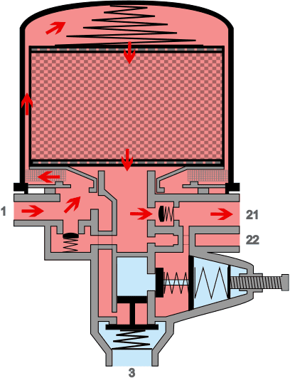
Pressure Regulation:
Within the air dryer is a pressure regulator that ensures the pressure cannot rise excessively. The air pressure in the channel after the check valve (at outlet 21) exerts a force on the pressure limiter’s membrane. The membrane is pressed against the spring force, moving the hollow plunger to the right. The hollow space is sealed, and the air reaches the area above the relief valve. The white arrows indicate the airflows responsible for this.
The incoming air pressure also exerts a force on this relief valve, causing it to open against the spring force.
The air compressor will move the air directly from connection 1, through the air dryer’s channels to connection 3. The dryer is now depressurized. The compressor will transfer air without pressure. The activation pressure is 1 to 1.5 bar lower than the deactivation pressure, preventing constant switching of the pressure regulator. The moment of activation and deactivation is called hysteresis, similar to electronics.
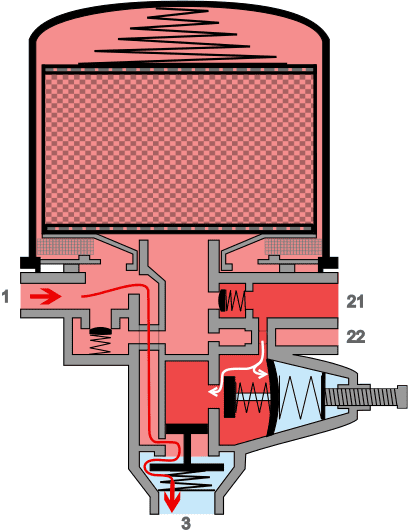
Regeneration:
When the pressure is regulated, the relief valve opens, and pressure in the air dryer drops. In the regeneration reservoir (connected to outlet 22), there is still a small supply of air under system pressure. The regeneration reservoir empties – via the bore in the dryer and the throttle – and blows dry and slightly warm air in the opposite direction through the filter element. The dry air will draw moisture from the granules and thus dry the granules. The moist air will be expelled through the coarse filter and relief valve into the atmosphere.
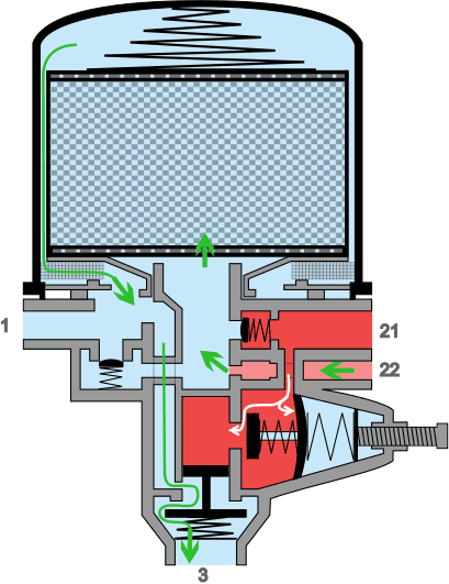
As the pressure in the installation continues to decrease, the pressure regulator reaches its activation pressure. The membrane of the pressure control valve is pressed to the left by the spring, sealing off the chamber above the relief valve. The spring above the relief valve presses the valve back onto its seat.
The compressor resumes supplying air through connection 1 on the dryer, and the process of pressure increase, regulation, and regeneration begins again.
Despite the granules being periodically regenerated, the drying capacity will gradually decrease. This is also because oil mist from the compressor flows with the air and adheres to the granules. Therefore, the element must be replaced during maintenance:
- after a certain number of driven kilometers;
- after a certain number of operating hours;
- periodically, regardless of the number of kilometers driven or operating hours, but typically every year.
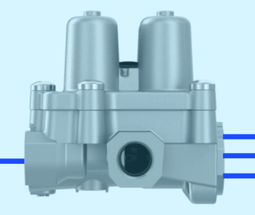
Four-Circuit Protection Valve:
The four-circuit protection valve is located between the air dryer and the air reservoirs. From inlet 1, the circuits are divided into four outlets: 21, 22, 23, and 24.
If a leak occurs in one circuit, the valve prevents all circuits from completely emptying. The remaining circuits will still function, but with lower pressure.
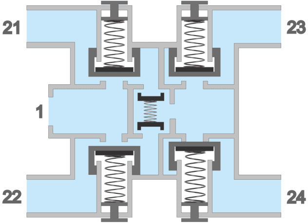
The following images show the diagram of the four-circuit protection valve with the symbol and codes.
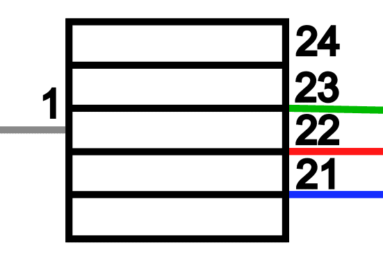
Legend:
1. Circuit Breaker Valve Circuit 1
2. Circuit Breaker Valve Circuit 2
3. Circuit Breaker Valve Circuit 3
4. Circuit Breaker Valve Circuit 4
5. Inlet
6. Check Valves for Circuit 3 and 4
Connections 21 to 24: Outlets Circuit 1 to 4.
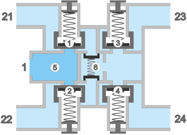
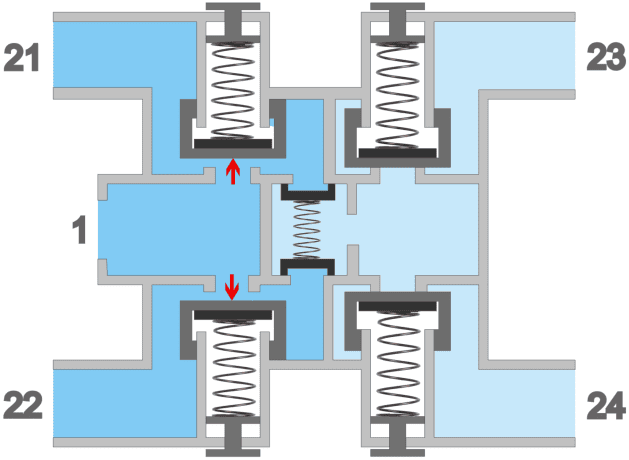
Inside the four-circuit protection valve, there are four circuit breaker valves (one for each circuit). The circuits for the service brake (1 and 2) are filled with air first. In the image below (1), the red arrows indicate the force exerted by the air pressure on the disc of the circuit breaker valves, pushing them against their spring pressure.
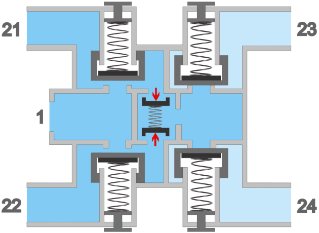
Upon reaching a certain pressure, the check valves of circuits 3 and 4 open, allowing air to reach the circuit breaker valves of circuits 3 and 4. In image 2, we see the air pressure pushing the check valves inward against the spring force, allowing air pressure to flow into the right chamber.
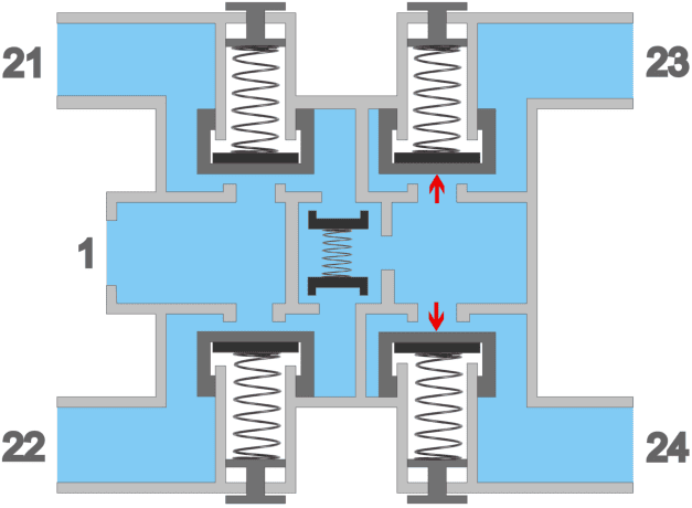
In the third image, we see the force exerted on the circuit breaker valves 3 and 4. In this situation, all four circuits are supplied with the same air pressure. This condition remains constant until the air pressure drops due to engine shutdown or in the event of a malfunction.
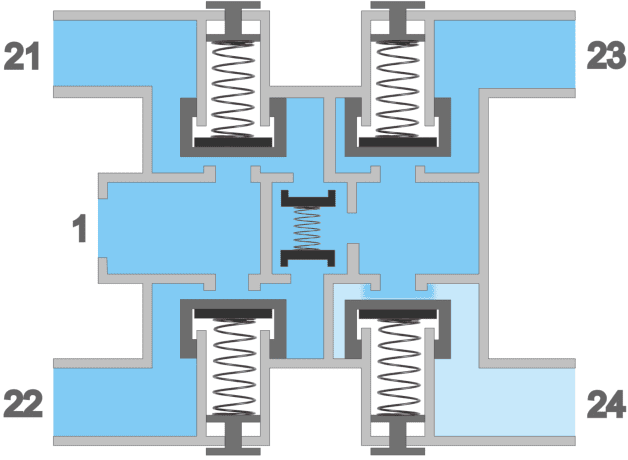
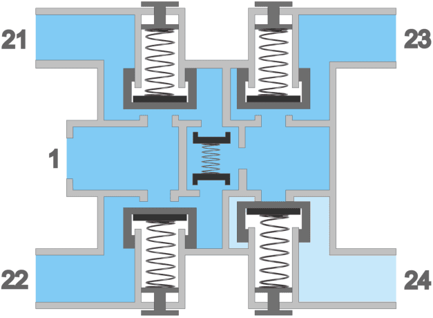
In the event of a leak in one of the circuits, the four-circuit protection valve prevents the complete emptying of other circuits. The three images below show what happens if circuit 4 leaks. In image 4, we see that the air pressure in circuit 4 drops, as indicated by the light blue color. Due to the pressure drop in circuit 4, there would initially be an effect on the pressure in the other circuits. The circuit breaker valve of circuit 4 closes (image 5), allowing pressure in other circuits to be restored. In image 6, circuits 1, 2, and 3 are supplied with air pressure from the compressor, while circuit 4 is isolated from the rest.
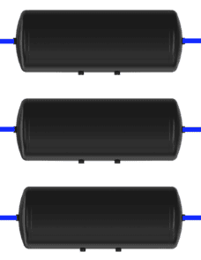
Air Reservoirs:
During braking, the air pressure is used which is transferred from the air supply to the air consumption section. After braking, the air pressure escapes into the atmosphere and cannot be reused. To brake again, new air is needed. To brake multiple times consecutively, a large amount of air is required, so it’s important to pre-store the needed air. This storage occurs in supply reservoirs, also known as air reservoirs. Each circuit has its own reservoir. The reservoirs are located between the four-circuit protection valve and the foot brake valve, relay valve, and check valve in the air consumption section.
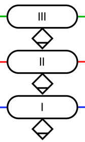
The images show three reservoirs stacked with the symbols of the reservoirs and drainage valves beside them.
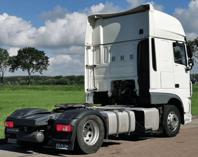
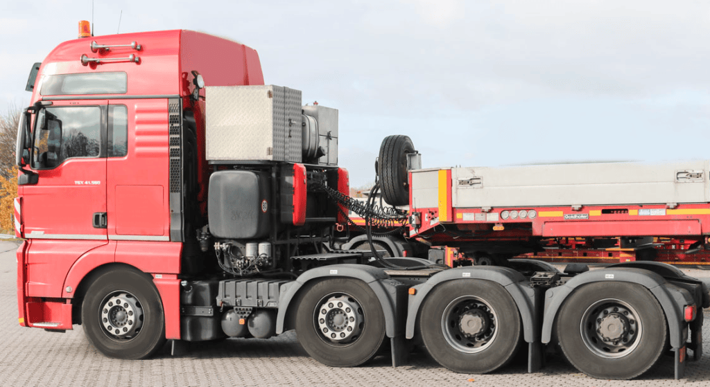
The images below show a DAF (left) with one of the air reservoirs at the rear of the chassis and a MAN (right) with two air reservoirs behind the front axle.
Related page: