Introduction:
A truck brake system has three main functions: reduce speed, bring the vehicle to a stop, and keep it stationary when parked. It differs from a passenger car because it uses pneumatics instead of hydraulics. The brakes are actuated by air from the pedal and the parking brake lever.
Heavy commercial vehicles and mobile machinery use air brakes, where the subsystems consist of:
- service brake
- emergency brake (auxiliary brake)
- parking brake
- continuous brake.
The first three subsystems are required by law.
With the service brake you can reduce the vehicle’s speed or bring the vehicle to a stop. Operated by foot, you must be able to modulate the braking force. Service brakes are friction brakes, which not only provide deceleration but also cause wear to brake linings, brake rotors, and brake drums. Wheel brakes convert part of the kinetic energy into heat (friction heat) and thus slow the vehicle down.
The emergency brake must ensure that braking is still possible if the service brake fails. The parking brake locks a stationary vehicle to prevent it from rolling away and operates mechanically, as required by law. It is operated with the parking brake lever on the dashboard, which can also function as the emergency brake. The parking brake is used to keep the parked truck in place and, by law, works mechanically by fully exhausting the spring brake chambers.
In addition to an air brake system, commercial vehicles usually also have a continuous braking system. Continuous brake systems, such as the retarder (engine brake), hydrodynamic retarder (driveline brake), and electromagnetic retarder (also a driveline brake), are supplementary braking systems that reduce speed without bringing the vehicle to a stop, without thermally (over)loading the mechanical brake components, when descending a mountain.
Air vs. fluid:
For passenger cars and light commercial vehicles, it is common to have brake systems that are powered by brake fluid. In the case of heavy commercial vehicles, however, a different approach is required due to the need for more braking power and the resulting heat build-up during braking events.
For trucks, brake components—especially drums—must be made larger to meet the required specifications. This includes not only a larger diameter but also a wider structure to provide space for more extensive brake linings. To prevent overheating of the brake linings, a substantial amount of lining material is needed to reduce the thermal load.
The larger surface area of the lining material is needed to create sufficient friction between the drum and the lining. This leads to the need for a large wheel cylinder, which, however, causes problems due to limited space for the brake lining. Increasing the diameter of the master cylinder is also not an ideal solution, because this can affect the desired braking force.
These limitations result in an increase in fluid flow and a longer piston stroke in the master cylinder. This in turn leads to increased pedal travel, reduced pedal feel, and a longer response time of the brake system. To overcome these challenges and meet legal requirements for braking deceleration in heavy commercial vehicles, a full air brake system is often chosen.
The advantages of a full air brake system include a minimal effect of temperature increase on the development of braking torque, a fast response time thanks to compressed air, and the ability to easily influence brake force development by adjustments to lever ratios or diaphragm chamber areas.
Air supply, air consumption, parking brake, and the components:
The service brake of a truck is made up of an air-supply section and an air-consumption section. In the image, the parts that belong to these sections are colored blue and yellow.
Air-supply section:
The air-supply section ensures that air is delivered at the correct pressure. In this section the air is also cleaned and dried. The components that belong to the air-supply section and are indicated in blue in the image below are:
1. Air compressor: the air compressor contains two cylinders in which air is drawn in and then fed under pressure to the next component;
2. Air dryer: this removes moisture from the compressed air. The filter contains granules that absorb the moisture. Under the dryer is the wet tank;
3. Four-circuit protection valve: when a leak occurs in one of the three circuits, the air pressure in the other two circuits is maintained;
4 through 6. Air tanks: the air supply is stored in the air tanks.
Air-consumption section:
In the air-consumption section, the air from the air-supply section is used. This section contains the controls, but also the control systems that regulate brake pressure depending on the load, and of course the brakes themselves. The air-consumption section is colored yellow.
7. Foot brake valve: the position of the foot brake valve determines how much air is allowed to the brake chambers. The driver operates the foot brake valve;
8. Load-dependent valve: the weight (load) on the rear axle is registered (mechanically or pneumatically). The ALR controls the relay valve;
9. Front diaphragm chambers: the brake calipers of the front wheels are actuated with diaphragm chambers.
10. Rear diaphragm chambers: the brake calipers or brake drums of the rear wheels are actuated by the diaphragm chamber, which is located in a combined spring brake chamber.
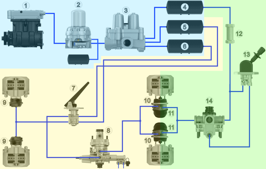
Legend:
1. Air compressor
2. Dryer with wet tank
3. Four-circuit protection valve
4. Air tank circuit 3
5. Air tank circuit 1
6. Air tank circuit 2
7. Foot brake valve
8. Load-dependent valve (ALR)
9. Diaphragm chambers (front)
10. Diaphragm chambers (rear)
11. Spring brake chambers (rear)
12. Check valve
13. Parking brake valve
14. Relay valve
- Blue: air supply
- Yellow: air consumption
- Green: parking brake / emergency brake
Parking brake and emergency brake:
In addition to the air-supply and air-consumption section, we also see the parking and emergency brake section in green. When the truck is parked, the driver can apply the parking brake. In an emergency, the emergency brake can be activated to bring the vehicle to a stop. The following components are found in the parking and emergency brake section:
11: Spring brake chamber: at rest, without air pressure, the spring in this combined spring brake chamber keeps the vehicle braked;
12: Check valve: this ensures that the brakes do not start dragging if a leak occurs in circuit 1, 2, or 4;
13. Parking brake valve: this lever is within reach in the dashboard. With this lever the parking brake can be (de)activated;
14. Relay valve: the amount of air from the parking brake valve determines the flow from tank 4 to the spring brake chambers 11.
Circuits in the air brake system:
The air brake system of a truck has three circuits:
- circuit 1: rear brakes
- circuit 2: front brakes
- circuit 3: parking brake / emergency brake
- circuit 4: accessories such as engine brake, air horn, and cab suspension
- circuit 5: air suspension. Previously, the air suspension was connected to circuit 4. On newer vehicles, this circuit is tapped off before the valve due to a higher pressure and fast response time.
The image below shows the three circuits of the brake system, which are separated in the four-circuit protection valve. The service brake consists of circuit 1 (blue for the front axle) and circuit 2 (red for the rear axle). Both circuits have their own air tanks (5 and 6 in the image), with the air pressure being about 10 bar. The parking brake / emergency brake (green) has its own air tank (4). The air pressure is about 8 bar.
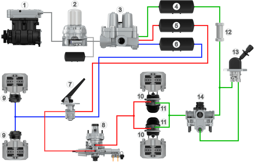
Legend:
Circuit 1: Red
Circuit 2: Blue
Circuit 3: Green
This overview does not yet include a trailer brake valve, because on this page we first focus on the basics of the air brake system of the truck. On the page: trailer brake the diagram above is expanded with, among other things, the trailer brake valve and the associated components and additional air lines.
Air brake port designations:
The air brake system of a truck consists of multiple circuits, such as those for the service brake, parking brake, accessories, and air suspension. When coupling a trailer, one circuit of the brake system is expanded. During maintenance, repair, or troubleshooting, it is important that the correct components and lines can be found. To keep things clear, all inlets and outlets of the valves are provided with designations. These designations show where the line comes from and where it goes. In line diagrams and function diagrams, the designations can be found.
0: Air compressor inlet connection
1: Air supply (inlet) to a component
2: Air delivery (outlet) from a component to another component
3: Vent / exhaust port to ambient air
4: Control port of a relay function of a valve
5: Free (often used from an air spring on EBS of a trailer)
6: Free
7: Frost protection
8: Lubricating oil (81: supply, 82: return)
9: Coolant (91: supply, 92: return)
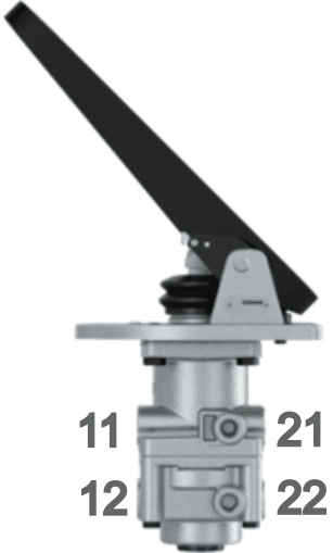
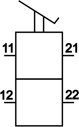
A component can have multiple inlets and outlets. The designation then consists of two digits, where the 1st indicates the type of port and the 2nd the sequence number. The foot brake valve, for example, has two inlets and two outlets for circuit 1 (front axle) and 2 (rear axle).
- inlet circuit 1: 11
- inlet circuit 2: 12
- outlet circuit 1: 21
- outlet circuit 2: 22
The following images show an illustration of a foot brake valve (drawing: Wabco) and the symbol of a foot brake valve, both with the designations.
In the images below we see the diagram of the air brake system with all components (top) and the diagram with the same layout in which the separated circuits with all symbols and designations of this particular brake system are shown (bottom).
Legend:
1. Air compressor
2. Dryer with wet tank
3. Four-circuit protection valve
4. Air tank circuit 3
5. Air tank circuit 1
6. Air tank circuit 2
7. Foot brake valve
8. Load-dependent valve (ALR)
9. Diaphragm chambers (front)
10. Diaphragm chambers (rear)
11. Spring brake chambers (rear)
12. Check valve
13. Parking brake valve
14. Relay valve
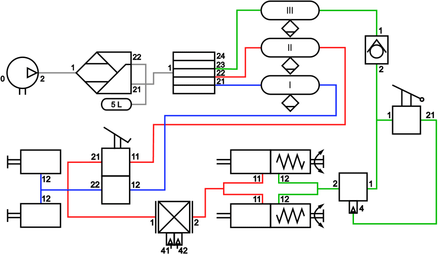
Legend:
Circuit 1 (rear brakes): Red
Circuit 2 (front brakes): Blue
Circuit 3 (emergency brake / parking brake): Green
Related page: