Introduction:
ABS (an acronym for Anti-lock Braking System) was already being successfully experimented with by tire manufacturer Dunlop in 1961 on the Ferguson P99 Formula 1 race car. This was about fourteen years before such technology was introduced in ‘normal’ cars. Nowadays, all new cars are equipped with ABS.
The purpose of ABS is to utilize the maximum grip between tire and road surface while driving. Additionally, ABS ensures that driving stability is maintained. This includes:
- Steering stability: when the ABS is activated, the vehicle remains steerable. With a slipping wheel, the vehicle slides in a direction, and steering movements cannot be transferred to the road surface.
- Course stability: a locked wheel can cause the vehicle to take another course. A locked rear wheel, for example, may cause the vehicle to spin around its axis, resulting in the vehicle facing backward on the road.
Operation:
The braking system is responsible for decelerating the wheels. The wheel must never lock, as it then loses grip with the road surface. In such a case, the wheel slides over the asphalt, and steering movements can no longer be transferred. Thus, the vehicle becomes unsteerable. The ABS system prevents the wheel from locking.
When the wheel is about to lock, the ABS system ensures that the braking pressure (the brake fluid pressure on the wheel brake cylinders) on the affected wheel is reduced. At that moment, it does not matter how hard the brake pedal is pressed. The ABS system adjusts the braking pressure to prevent the wheel from slipping. At a certain point, the ABS system gradually builds up the pressure again, as the wheel needs to be maximally decelerated. This process continues until the slip threshold is reached again, after which the pressure is reduced once more. This process takes a few milliseconds. At this point, a vibration can be felt in the brake pedal. Often, the ABS pump can also be heard.
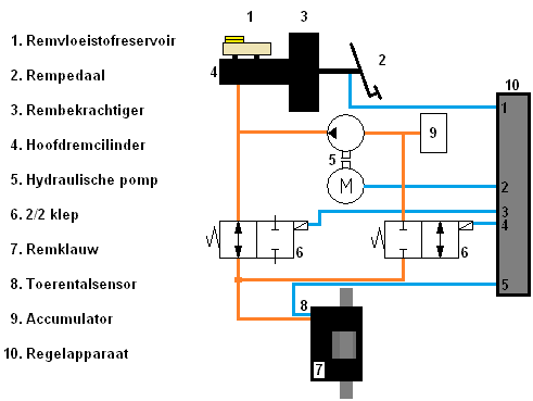
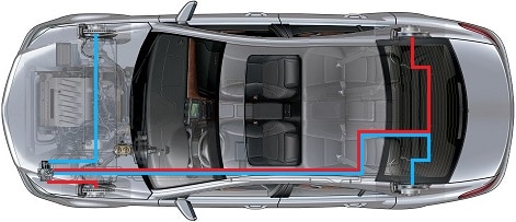
The following image provides an overview of the components of the ABS system.
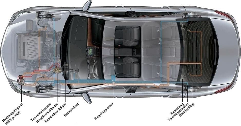
In the above image, two red lines are depicted. These run from the master brake cylinder to the hydraulic unit. The hydraulic unit is another word for the ABS pump. The two red lines are related to the split brake system; front left with rear right and front right with rear left. If, for example, there is a leakage at the left front wheel causing all brake fluid to leak out, braking is still possible with the other brake circuit. From the hydraulic unit, orange lines run to all wheels. In the hydraulic unit, the braking force can be adjusted for each wheel.
Each wheel has a speed sensor mounted. This allows for continuous monitoring of the speed of all four wheels. The blue lines are signal wires connected to the speed sensor. From each wheel, a signal wire runs to the control unit. Signals from the brake pedal and the hydraulic unit also go to the control unit. In the depicted vehicle, this is located under the seat, within the car’s interior. Nowadays, it is increasingly common for the control unit to be attached to the hydraulic unit, making it one entity. If a system malfunction is present, such as due to a defective or dirty sensor, faulty cable, or a defect in the hydraulic unit, a warning light on the instrument panel illuminates. The issue can then be read with diagnostic equipment.
Speed Sensors:
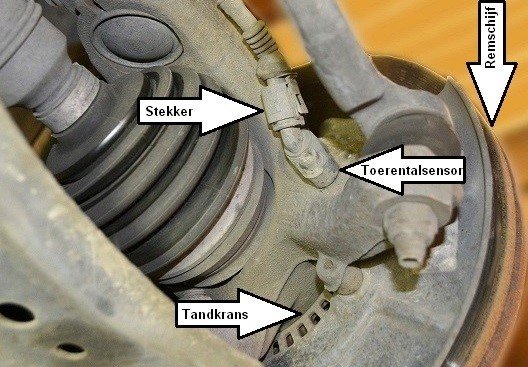
In the image below, the inductive speed sensor is visible in its mounted position. This is a photo of a McPherson strut from the front suspension. The gear ring, which the sensor measures the speed of, is also visible here.
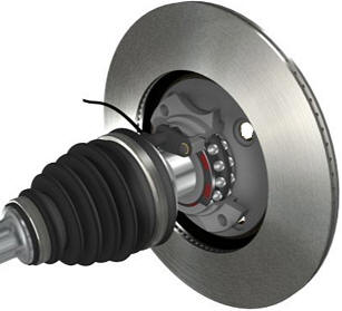
An ABS sensor can be executed as an inductive sensor (see above image), or as a magneto-resistive sensor (MRE sensor), also known as a Hall sensor (see image on the right). The operation of this sensor is described on the Hall sensor page. The latter sensor is applied to the ABS magnet ring, which is integrated into the wheel bearing.
The signals from the inductive and Hall sensors can be measured with the oscilloscope. Examples of these measurements are shown and described below.
Inductive Speed Sensor:
The inductive speed sensor consists of a permanent magnet with a coil around it. The magnetic field strength changes when a tooth of the gear ring (attached to the drive shaft) moves through the magnetic field of the permanent magnet. The change in the magnetic field induces a voltage in the coil. Each period in the speed signal corresponds to the passing of a tooth along the sensor. The number of teeth on the ring and the rotational speed of the drive shaft determine the frequency and amplitude of the signal.
Hall Sensor:
The magneto-resistive sensor (MRE sensor), or Hall sensor, also operates with a metal ring with magnets moving past the sensor. The magnet ring is located on the drive shaft or in the wheel bearing. The frequency of the block voltage depends on the rotational speed and the number of teeth on the metal ring. The amplitude (height of the signal) remains constant.�a0
MRE sensors require a supply voltage to operate. However, these sensors often have only two wires (and thus two connections). The sensor sends the signal via the ground wire to the ABS control unit. The signal is formed because the electrical resistance of the semiconductor plates changes when exposed to a varying magnetic field.
The signals from the speed sensors are transmitted to the ABS control unit. The signals from four wheels are compared. When the vehicle is driving through a curve, the wheel speed on the inside of the curve will be lower than that of the wheels on the outside. This is measured but falls well within the margins.
If the wheel speeds differ too much during braking, the ABS control unit ensures that the hydraulic unit reduces the braking pressure on the respective (over-braking) wheel. If there is too much wheel speed difference during acceleration, engine power will be abruptly reduced by the engine management system.
In case of malfunctions in the ABS system, signals can be measured with the oscilloscope. These can be measured at the wheel or at the control unit. Measuring at the wheel can check whether the ABS sensors are working properly. When measured at the control unit, it can be determined whether defective wiring is the cause of the malfunction.
During measurement, it can be checked if the frequency and amplitude of the inductive sensor are correct. For the Hall sensor, it can be verified whether the frequency of the signal is correct while rotating the wheel. Rotate the wheel fully to quickly detect any defects in the teeth. Damaged teeth will show a deviation in the clarity of the sensor signals (think of a frequency that gets broader with each rotation than intended).
Hydraulic Unit:
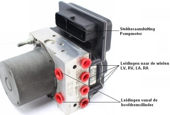
The image at the bottom left shows a hydraulic unit with a built-in control unit. This is evident from the large number of pins in the connector.
The connections of the lines from the master cylinder to the wheels are also visible here. The separated braking circuits (front left with rear right and front right with rear left) are incorporated into this pump unit.
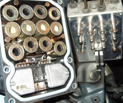
When we disassemble the hydraulic unit, the valve block is visible. The image at the bottom right shows the interior of the hydraulic unit.
Hydraulic Circuit:
In the hydraulic diagram below, the components in and around the hydraulic unit are visible. To understand the operation, parts, and symbols, the page basic principles of hydraulics may be consulted.
The following diagram is drawn for one wheel. Numbers 5, 6, and 9 are internal. Another wheel uses, except for the 2/2 valves (6), the same components, only with other connections. In other words, if the diagram of the entire car were drawn, there would be six more 2/2 valves with their own lines. To keep it clear, only the diagram for one brake circuit is depicted now.
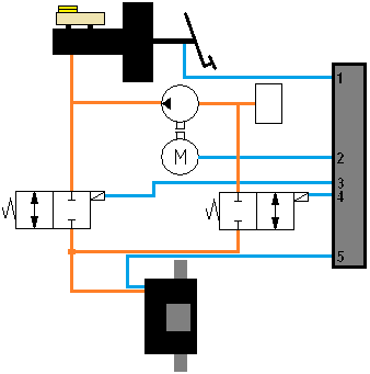
Situation 1: Not Braking and Stable Braking:
The diagram on the right indicates the situation during not braking and stable braking. The brake pedal (2) is depressed, causing fluid pressure from the master cylinder (4) to be applied to the left 2/2 valve (6). This 2/2 valve has an open connection to the brake caliper (7). As the fluid pressure to the brake caliper increases, the brake pads are pressed against the brake disc. The vehicle will be braking. The speed sensor (8) records the number of revolutions the wheel makes.
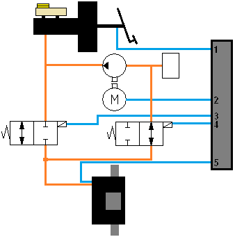
Situation 2: ABS Active, Hold Braking Pressure:
This diagram depicts the situation when braking firmly and the wheel deceleration is too great. The ABS sensor at the brake has transmitted a speed signal to pin 5 of the control unit, which is lower than the other wheels. The control unit responds by closing the system to the brake caliper.
This happens as follows: a certain current is applied to pin 3 of the control unit, causing the solenoid on the left 2/2 valve to be energized. The valve is pushed to the left against the spring force. This blocks the access of new brake fluid to the brake caliper. The right 2/2 valve remains in the same position, so neither brake fluid can flow to the brake nor return. The pressure is therefore kept constant. The control unit reassesses the speed difference between the affected wheel and the other wheels. If the inter-wheel speed difference is minimal or there is no longer a speed difference because the braking pressure has been held constant, the control unit removes the current from pin 3. The 2/2 valve springs back to its original position, reverting to situation 1. If the speed difference does not change or becomes even larger, the brake pressure for the affected wheel must be reduced. This occurs in situation 3.
Situation 3: ABS Active, Reduce Braking Pressure:
To reduce the braking pressure, brake fluid in the line between the 2/2 valve and the brake caliper needs to be pumped away. This is shown in the above diagram.
Now, pin 4 is also supplied with current, energizing the right 2/2 valve. This is also shifted to the left position, allowing the passage between the brake caliper and the hydraulic pump to open. At this moment, the pump motor starts running and pumps the brake fluid from the brake caliper back to the master brake cylinder. The fluid is pumped back against the force of the master brake cylinder into the reservoir. The pressure is reduced, allowing the wheel to start rotating again.
Summary:
While driving and light braking, situation 1 applies. During braking when the wheel is about to lock, situation 2 applies and when the pressure needs to be reduced due to the locking wheel, situation 3 applies. During braking, the situation will change continuously. If situation 3 is applicable, where brake fluid is pumped away from the brake, the wheel must then be decelerated again. Otherwise, the vehicle will not be able to brake powerfully enough. It will then return to situation 1, followed by situation 2, and then situation 3 again. This continues until the driver stops braking or until driving on another surface that is, for example, rougher (a higher coefficient of friction).
ABS Control Cycle:
The control cycle of the ABS is depicted in the graph below. It includes various factors such as vehicle speed (A) with wheel speed, wheel circumferential acceleration (B), system activity (C), and brake pressure (D).
The graph is also divided into 9 time periods. In each period, a change is visible as the system adjusts. The total time period is approximately 20 milliseconds and is divided into 9 unequal parts. The explanation of the lines is provided below the graph.
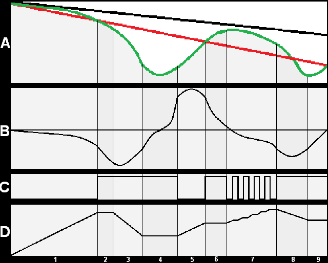
A: The black line represents vehicle speed, the green line represents wheel speed, and the red line represents reference speed. Vehicle speed decreases (period 1), but wheel speed decreases much faster. Additionally, the red reference line is intersected. When the green line falls below the red line (from period 2), wheel slip can occur. The ABS will then intervene.
B: The line indicates wheel circumferential acceleration. For example, by rotating the wheel and braking slowly, the line at B stays close to the zero line. By rotating the wheel at the same speed and braking more forcefully, the line will deflect further downward. This also occurs when speeding up; by rotating the wheel very quickly from 0 to 10 km/h, the line will shoot up more than if it takes 5 seconds to rotate the wheel from 0 to 10 km/h. In short, this is wheel circumferential acceleration.
C: This line indicates where the pressure in the system is stabilized; the ABS is then in operation. Where the line at C is low (on the zero line), the ABS system is not in operation. In period 7, the ABS is pulsed, preventing the wheel speed from decreasing too quickly.
D: This line represents brake pressure. Brake pressure increases until the green line (A) of wheel speed intersects with the red reference line. The ABS activates (C) and ensures that wheel circumferential acceleration does not fall too low. Wheel circumferential acceleration is at the zero line in period 4; precisely when wheel speed in (A) shifts from negative to positive. Pressure is kept constant at that moment. In period 7, the pulsed control is clearly visible. Brake pressure is cautiously increased so that the wheel does not decelerate too quickly.
Control Principles to Prevent µ-Split:
The ABS can be set individually for each wheel using this information. Wheel speed sensors register the speed of each wheel. This is necessary because in all situations, the maximum achievable friction coefficient must be weighed against the vehicle’s steerability. When the vehicle has its left wheels on dry asphalt and the right wheels in the soft shoulder and fully brakes, it will become unsteerable and spin around its axis. The difference in braking force between the wheels on asphalt and on ice causes a yaw moment that results in a course deviation. This situation is called the µ-split situation. µ is pronounced as “mu”.�a0To prevent this scenario, several control principles are applied:
- The individual regulation (IR): here, the brake pressure is set to the maximum friction coefficient of each wheel. This can result in high yaw moments but achieves maximum braking forces.
- The select-low control (SL): the wheel with the lowest friction coefficient determines the brake pressure for the other wheel. Although the maximum achievable braking force is not used, the yaw moment is low.
- The select-high control (SH): the wheel with the highest friction coefficient determines the brake pressure for the other wheel. Select-high control is only used for ASR adjustments.
- The select-smart or modifying control: during braking, it adjusts from select-low to individual regulation. This allows for a compromise between yaw moments and maximum braking forces. This control is often applied to commercial vehicles.
Typically, the braking system of a passenger car is diagonally (crosswise) separated. An example is shown in the image below. Here, the red braking system is for front left and rear right, and the blue braking system is for front right and rear left.
The brakes of the front wheels are controlled with individual regulation (IR). The brake pressure of one front wheel is set to the maximum friction coefficient of the other front wheel. During an emergency stop, the front wheels will individually seek the maximum achievable braking force.
The brakes of the rear wheels are controlled according to the select low (SL) principle. The regulated brake pressure of the rear wheel with the least friction coefficient determines the brake pressure of the other rear wheel. The braking torque of both rear wheels will remain the same.
Measurements of a Vehicle With and Without ABS:
To get a clear picture of the influence of the ABS system on a vehicle, this section presents two graphs of measurements that demonstrate the difference of a decelerating vehicle without and with ABS.
Vehicle Speed Compared to Wheel Speed Without ABS:
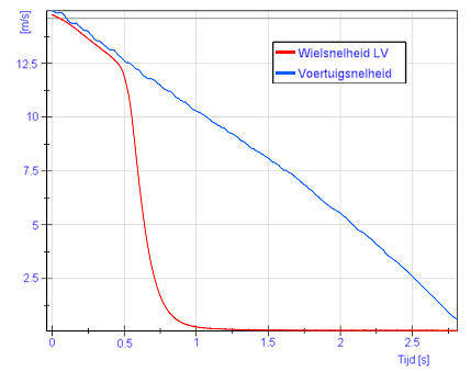
In the graph on the right, vehicle speed compared to wheel speed is shown.
From t = 0 seconds, the vehicle speed is 15 meters per second. At that moment, the brake pedal is pressed to the maximum. The vehicle speed decreases linearly to 0 m/s between
t = 2.75 and 3.00 seconds. The wheel speed completely drops to 0 m/s between t = 0.5 and 1.0 seconds. This means that the wheel already has a speed of 0 m/s, thus is stationary while the vehicle is still moving. At that moment, a wheel is locked. The wheel skids on the road surface while the vehicle is not yet stationary. In this situation, ABS is therefore not active.
Vehicle Speed Compared to Wheel Speed With ABS:
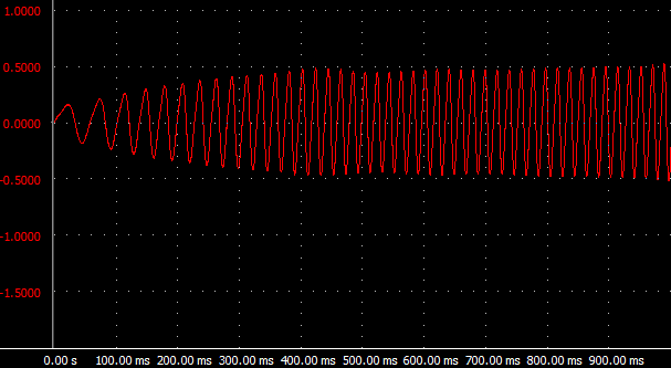
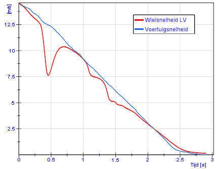
In the graph on the right, the blue line behaves the same; at a vehicle speed of 15 m/s, it is braked to 0 m/s as much as possible. This again occurs over a period of 3 seconds. With ABS in operation, the red line at t = 0.3 seconds does not drop to 0 m/s, but the wheel speed increases again. This is seen in the red line initially going down and then rising slightly before t = 0.5 seconds. The ABS reduces brake pressure at a speed of 7.5 m/s. The speed of the other wheels is equal to the vehicle speed and thus to the blue line. The ABS sensor of the left front wheel registers the deceleration. The ABS computer recognizes the speed difference, thereby intervening. Brake pressure is reduced by the hydraulic unit until the blue and red lines are equal again. At that point, brake pressure is maintained. Until the vehicle stops, ABS keeps regulating the speed of the slipping wheel.
The Pressure in the Master Cylinder Compared to Wheel Brake Cylinder Without ABS:
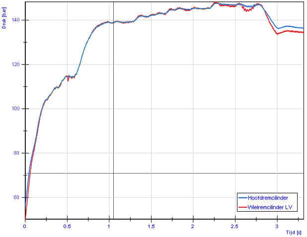
The force exerted on the brake pedal is converted into brake pressure in the master cylinder through fluid displacement. This brake pressure is represented by the blue line in the graph below.
Regardless of whether the wheel slips or not, brake pressure in the wheel brake cylinder (the red line) remains equal to the pressure in the master cylinder. This is the situation without ABS.
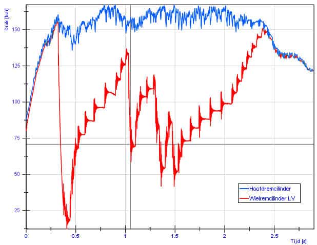
The Pressure in the Master Cylinder Compared to Wheel Brake Cylinder With ABS:
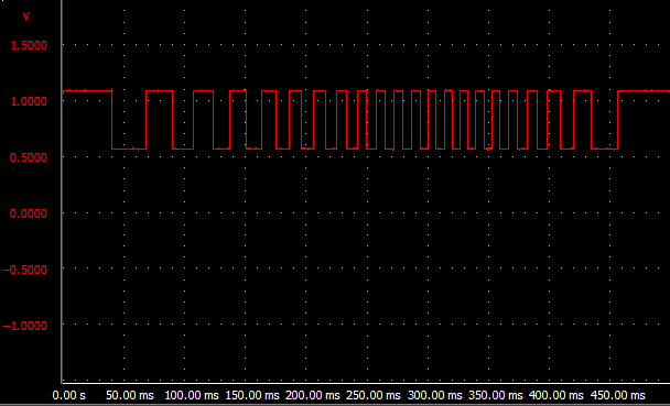
In the situation where ABS engages, the pressures in the master cylinder and in the wheel brake cylinder are no longer equal. The pressure in the master cylinder remains high, as the driver keeps the brake pedald epressed. In the graph, the red line drops at t = 0.3 seconds; here, the ABS reduces the brake pressure. The reduction in pressure ensures that the wheel rolls again. From t = 0.4 seconds, brake pressure is increased stepwise until the speed of the wheel equals the other wheels. This occurs at t = 2.35 seconds.