Introduction:
Modern diesel engines are subject to increasing demands. Consumers seek more comfort and power, while governments and other agencies enforce stricter environmental standards. Car manufacturers are compelled to innovate cleaner and more fuel-efficient engines that also deliver more power. Examples include the common-rail and unit injector fuel injection systems. The unit injector system was developed by Volkswagen.
Volkswagen employed the unit injector technology for the:
- 1.2 TDI,
- 1.4 TDI,
- 1.9 SDI,
- 1.9 TDI 105, 110, 115, 130, and 150 hp,
- 2.0 TDI,
- 2.0 SDI,
- 2.5 R5 TDI,
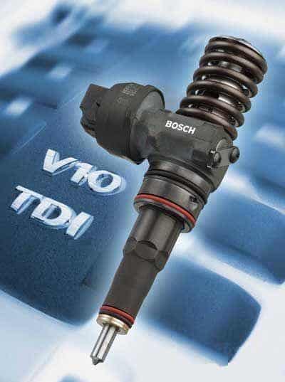
- 5.0 V10 TDI.
Due to emission requirements, new cars no longer use unit injectors, replacing them with common-rail systems.
Operation:
The unit injector system is a direct fuel injection system. An electronic fuel pump delivers diesel with a pressure of approximately 7.5 bar from the tank to the fuel supply of the unit injectors. This pressure fills the pump element. The pump element of the unit injector is operated by the camshaft via a rocker arm. Pressure builds in the pump element when the rocker arm pushes the injector needle down. The quantity of injected fuel is controlled by the solenoid valve; the longer the control unit activates the solenoid valve, the more fuel is