Introduction:
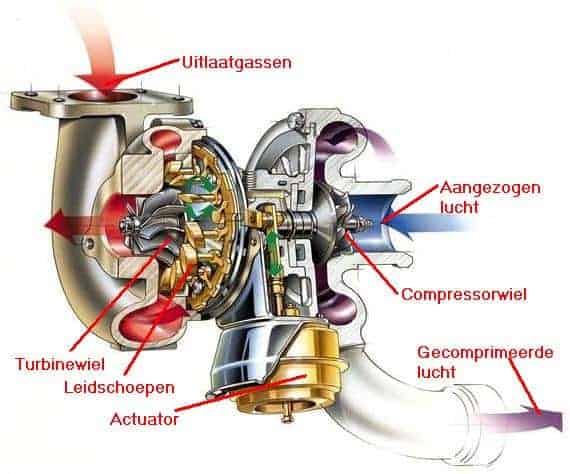
The exhaust gases leaving the cylinders are routed to the turbo via the exhaust manifold. The pressure and energy of these exhaust gases cause the turbine wheel to spin. After the exhaust gases have transferred energy to the turbine wheel, they leave the turbo and flow on toward the exhaust system.
The turbine wheel is connected to the compressor wheel via a shaft. When the turbine wheel spins, it drives the compressor wheel. The compressor wheel draws in air through the intake on the side of the turbo, where the air filter is located. This air is compressed and routed under pressure through the turbo hose to the intercooler.
By using a turbo, more air enters the cylinders during the intake stroke than with a naturally aspirated engine. In a naturally aspirated engine, air is drawn in only because the piston moves downward.
In a turbocharged engine, the air is actively forced into the cylinders under pressure. Because there is more air in the cylinders, more fuel can also be injected. This releases more energy during combustion, resulting in higher engine power.
Boost pressure is measured by the boost pressure sensor. This sensor sends a signal to the ECU. Based on this signal, the ECU regulates the boost pressure, for example by actuating the wastegate or a variable turbine geometry.
The turbo is installed as close as possible to the exhaust manifold. Sometimes the exhaust manifold and the turbo therefore form a single unit. Immediately after leaving the combustion chamber, the exhaust gases still have a high gas velocity. This ensures that as little energy as possible is lost before the exhaust gases reach the turbine wheel. This limits pressure loss and ensures efficient driving of the turbine wheel. Because of the short distance between the cylinders and the turbine wheel, the volume of the exhaust tract is small, allowing the turbo to respond more quickly to changes in engine load. The turbo shaft can therefore spool up faster, which reduces turbo lag.
The temperature of the air compressed by the turbo can rise significantly, often to above 60 degrees Celsius. For good combustion, it is important that this air is cooled. This increases air density, providing more oxygen for combustion.
The intercooler cools the compressed intake air before it enters the engine. The intercooler is a separate component and is therefore discussed in detail on a separate page; see the page Intercooler.
Multiple turbos:
The term ‘twin-turbo’ indicates the presence of two turbos. Those 2 turbos can be mounted side by side on one cylinder bank, or one turbo per cylinder bank. This gives the driver the advantage of higher torque at low engine speeds, better performance at high engine speeds, and a smoother engine character. At low rpm, the air is supplied to the engine by a small turbo, and at higher rpm the larger turbo becomes effective. The larger turbo has more turbo lag because it needs more air to get going, but that is offset by the small turbo.
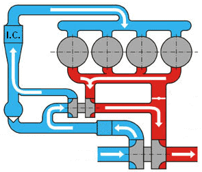
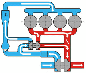
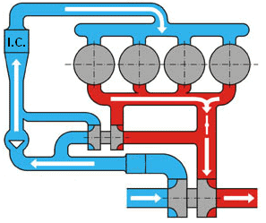
In the four images below, the situations are described in which both turbos are working, or when only one of the two is working. The four circles are the cylinders; the red and blue parts are the exhaust gases and intake air. The intercooler is indicated with “I.C.”.
Low engine speed and low engine load:
At engine speeds below 1800 rpm there is a small volumetric flow of exhaust gas. With this small volume, the small turbo can be used. The valve between the exhaust manifold and the large turbo is closed. The exhaust gas is therefore transferred only from the small to the large turbo. This already brings the large turbo up to speed. This is a series arrangement, because both turbos are used.
Medium engine speed and moderate load:
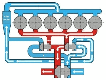
Between 1800 and 3000 rpm, the valve between the exhaust manifold and the large turbo opens. At this moment, both turbos are driven directly by exhaust gases from the engine. Here too, this is a series arrangement, because both turbos are used.
High engine speed and high load:
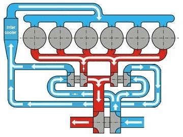
Above 3000 rpm, the volumetric flow of exhaust gas becomes too large for the small turbo. The turbo is switched off to avoid crossing the so-called “chokeline” (see the compressor characteristic chapter further down the page). The wastegate of the small turbo is opened, so that all exhaust gas that is fed toward the turbo is routed past the turbo. The exhaust gas therefore does not reach the compressor wheel.
The large turbo, however, is fully supplied with exhaust gas. The valve remains open so that the large turbo can reach a high speed and thus move a lot of intake air to the intake manifold.
Nowadays, “tri-turbo” engines are also being produced. These engines have three turbos fitted so that maximum volumetric efficiency can be achieved in every rpm range. BMW uses tri-turbo technology in, among others, the M550d. The two small turbos use variable geometry, making them suitable for both low and high engine speeds. Depending on engine speed, the turbo is adjusted for better response. The large turbo uses a wastegate.
Below, two situations are described indicating which turbo is operating at which moment.
Low engine speed and low load:
Only one of the two small turbos is driven. Due to the turbo’s size, it spools up quickly. The small turbo routes the exhaust gas through to the large turbo. This already gets the large turbo going.
Medium and high engine speed and load:
Both small turbos are driven. The two small turbos drive the large turbo. This achieves maximum boost pressure at all medium and high engine speeds.
Boost pressure control with the wastegate:
On virtually every turbo without variable vanes, a wastegate is fitted. The wastegate ensures that the pressure and speed of the turbo do not become too high. It does this by routing part of the exhaust gases past the turbine wheel, so these gases do not contribute to driving the turbo. When the turbo still needs to build pressure, for example during acceleration, the wastegate is closed. All exhaust gases leaving the cylinders during the exhaust stroke then flow through the turbine wheel. This allows the turbo to spool up quickly and the desired boost pressure to be built.
At idle, little or no boost pressure is required. In this situation, the wastegate is (partly) open. Part of the exhaust gases is then routed directly to the exhaust system, without flowing through the turbo. The energy of these exhaust gases is not used to drive the turbo. This is where the wastegate gets its name; the English word “waste” means loss. At higher engine speeds and load, the wastegate can also open. As soon as the turbine wheel, and therefore the compressor wheel, reaches a certain speed or a maximum boost pressure, further increase must be prevented. By partially opening the wastegate, part of the exhaust gases is diverted. In this way, the turbo speed and boost pressure remain within safe limits.
The extent to which the wastegate opens is controlled by the ECU. For this, the ECU uses, among other things, the signal from the boost pressure sensor. By varying the opening angle of the wastegate, the boost pressure can be regulated accurately.
The image below shows boost pressure control with wastegate adjustment. The vacuum pump (2) supplies vacuum to both the brake booster (4) and the wastegate actuator on the turbo (7). The one-way valve (5) ensures that airflow can go only one way: vacuum can be drawn from the wastegate, but if the vacuum on the brake booster side partially drops, for example after repeated (pumping) braking and the vacuum pump has not yet generated sufficient vacuum, it will have no influence on boost pressure control. The explanation of boost pressure control continues below the image.
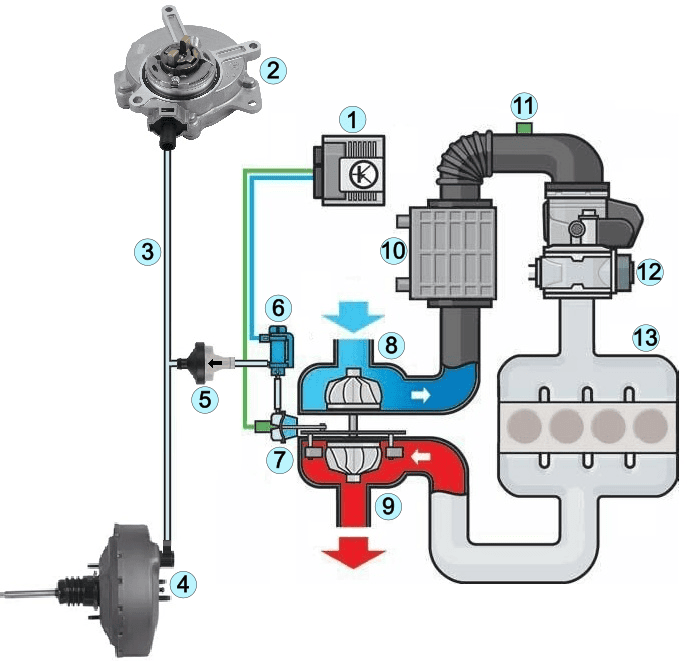
Legend:
- Engine control unit (ECU)
- Vacuum pump on the camshaft
- Vacuum line
- Brake booster
- One-way valve
- PWM-controlled boost pressure control valve (N75)
- Wastegate actuator on the turbo
- Turbo inlet (compressor side)
- Turbo outlet (turbine side)
- Intercooler
- Boost pressure and temperature sensor
- Throttle body
- Intake manifold of the internal combustion engine
The PWM-controlled boost pressure control valve (N75) regulates the amount of vacuum that is allowed to the wastegate actuator on the turbo (7). The engine operating conditions determine the wastegate opening angle:
- during acceleration at low rpm, the wastegate is fully closed to bring the turbine shaft up to speed as quickly as possible;
- when higher boost pressure is reached, measured by the boost pressure sensor (11), the wastegate opens partially or fully to limit boost pressure.
The wastegate is a normally-open valve: without actuation it is open and the turbine wheel does not build pressure. The exhaust gases leave the turbo via the wastegate to the exhaust and do not drive the turbine wheel. Only when vacuum has been built up and the boost pressure control valve (6) gradually allows the vacuum through does the wastegate close against the spring force.
A vacuum pump can be used to check the vacuum to the wastegate. When the engine idles for a few seconds and the pressure on the vacuum line is measured, the pressure is around 100 to 250 millibar (-0.1 to -0.25 bar).
Suppose there is a fault in the boost pressure adjustment and we measure a pressure around atmospheric pressure of 1 bar, then insufficient vacuum has been built up. We can connect the pressure gauge at several points to investigate whether the vacuum pump is not functioning properly, the one-way valve is defective (blocked), there is an air leak in the vacuum line, or the boost pressure control valve (N75) is not functioning properly.
Twin-scroll turbo:
When exhaust gases from multiple cylinders come together in the exhaust manifold, interference problems can arise. The pressure waves from different cylinders can then disrupt each other, causing energy to be lost before the exhaust gases reach the turbine wheel.
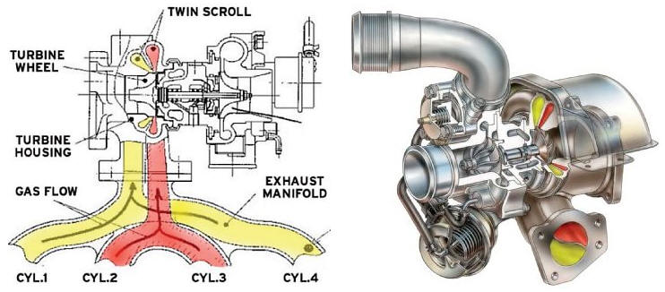
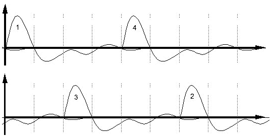
In a twin-scroll turbo, the exhaust gases are separated and routed to the turbo via two separate channels. This means that the exhaust gases from certain cylinders do not come into direct contact with each other in the exhaust manifold, but reach the turbine wheel separated from each other. In this way, the pressure pulses are better preserved and the turbine wheel is driven more efficiently. Using a twin-scroll turbo provides faster throttle response and higher turbo efficiency. The image below shows that the exhaust gases from cylinders 1 and 4 form one channel and those from cylinders 2 and 3 form the other channel. This prevents interference between the pressure waves as much as possible.
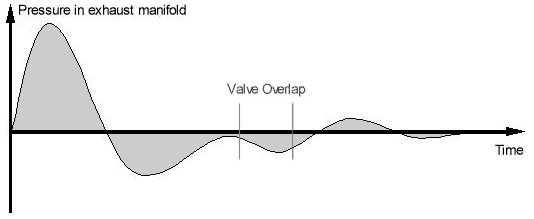
With a conventional turbo, the exhaust gases come into contact with each other in the exhaust manifold. We call this “interference”. The image below shows the pressure pulses that arise in the exhaust manifold from one cylinder.
Because there is valve overlap—where during the transition from the exhaust stroke to the intake stroke both the intake and exhaust valves are open—temporary vacuum conditions can occur in the cylinder. This pressure can be lower than atmospheric pressure. During valve overlap, the exhaust gases help draw fresh intake air into the combustion chamber and expel remaining exhaust gases. This phenomenon is also known as scavenging. This improved scavenging fills the combustion chamber with more fresh air and therefore more oxygen. This increases the engine’s volumetric efficiency.
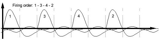
When we look at the pressures in the exhaust manifold of a four-cylinder engine, we see that a lot of interference occurs. The pressure pulses from the different cylinders influence each other. Each positive pressure pulse is partially flattened by negative pressure waves that arise as a result of valve overlap. This interference causes the effective energy of the exhaust-gas pulses to decrease. As a result, the turbine wheel is driven less forcefully, which has an adverse effect on the turbo’s spool-up time. This increases turbo lag, i.e., the response time needed to build up sufficient boost pressure.
Using a twin-scroll turbo improves the turbo’s response time because the exhaust gases from cylinders 1 and 4 and from cylinders 2 and 3 are separated from each other. As a result, the exhaust-gas pulses are preserved better and are less affected by negative pressure waves from other cylinders. The pulses that reach the turbine wheel are therefore stronger and more energetic.
Because the exhaust-gas pulses are utilized more effectively, the manufacturer can choose to increase valve overlap. This enables better scavenging of the cylinders, allowing more fresh air to be drawn in. The result is higher volumetric efficiency and a faster turbo response.
Variable geometry turbo (VGT):
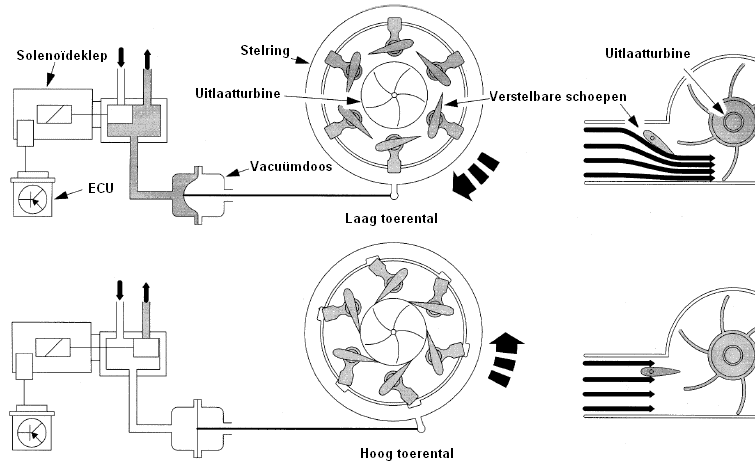
A turbo with a wastegate may suffer from turbo lag. Only when the engine reaches a certain speed is enough exhaust-gas energy available to spool the turbo up quickly. At low engine speeds, exhaust-gas pressure is often too low to drive the turbo effectively. A variable geometry turbo does not have a wastegate, but is equipped with adjustable vanes in the turbine housing. These vanes can change position by means of an adjusting ring. The adjusting ring is usually rotated using vacuum. The required amount of vacuum is determined by the ECU based on engine load and engine speed and controlled via a solenoid valve.
By changing the position of the vanes, the flow of the exhaust gases can be directed. At low engine speeds the vanes are more closed. This makes the passage smaller and increases the velocity of the exhaust gases, causing the turbine wheel to spin faster despite the lower exhaust-gas pressure. This significantly reduces turbo lag. At higher engine speeds the vanes are opened further. This allows a larger amount of exhaust gas to flow through the turbo without the turbo spinning too fast. In this way, suitable boost pressure can be built up at both low and high engine speeds. The engine already has sufficient boost at low speeds, while at high speeds turbo overloading is prevented.
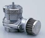
Dump valve:
The dump valve is also called a blow-off valve. The dump valve is mounted in the intake tract between the turbo and the engine’s intake side. Via this tract, the compressed air from the turbo is fed to the engine. During acceleration, the turbo of a passenger car can reach speeds of up to about 200,000 revolutions per minute, at which the maximum boost pressure is built up.
When the accelerator pedal is suddenly released, the throttle valve closes. However, at that moment the turbo is still spinning at a high speed and continues to supply air. This creates an overpressure in the intake tract upstream of the throttle. Without a dump valve, this overpressure would flow back toward the compressor, strongly braking the compressor wheel. This phenomenon is called compressor surge and causes the turbo speed to drop quickly.
The dump valve prevents this by venting part of the compressed air when the accelerator pedal is released. This removes the overpressure from the intake system and prevents the air from pushing back against the compressor wheel. As a result, the turbo maintains its speed better, so that boost pressure is available again more quickly when the throttle is reopened. Once the overpressure has been discharged, the dump valve closes again.
Contrary to what is often thought, a dump valve does not provide higher engine power. The function of the dump valve is to protect the turbo and improve throttle response. The characteristic venting sound that can be heard when releasing the accelerator pedal during acceleration is caused by the opening of the dump valve.
Compressor map (surge- & choke line)
When designing an engine, the size of the turbo must be taken into account. Matching the size of the turbo to the engine is called “matching”.
- With a too large turbo, turbo lag is large. The turbo spools up slowly because the turbine housing and turbine wheel are too large for the small amount of exhaust gas at low engine speeds. Only at higher speeds is there enough exhaust-gas energy available to bring the turbo up to speed and deliver high boost pressure.
- With a too small turbo, turbo lag is small or virtually absent. The turbine wheel spools up quickly even with a small amount of exhaust gas. As a result, relatively high boost pressure is already built up at low engine speeds. The disadvantage of a turbo that is too small is that at higher engine speeds the amount of exhaust gas becomes too great for the turbo. The turbo can no longer process this amount of energy.
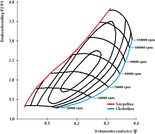
In that case, the wastegate must open earlier to route some of the exhaust gases around the turbine. This prevents the turbo from reaching excessively high speeds. The word waste means “loss”. This applies here because the exhaust gases diverted via the wastegate do not contribute to driving the turbo and therefore do not deliver useful power. The size of the turbo is therefore very important in engine design. Every turbo has a specific compressor map. Based on this compressor map, it can be assessed whether a turbo is suitable for a particular engine. The image below shows an example of a compressor map.
The pressure ratio P2/P1, shown on the y-axis, is the ratio between the pressure upstream of the compressor (P1) and the pressure downstream of the compressor (P2).
- P1 is the compressor inlet pressure. This is usually ambient pressure or the pressure after the air filter.
- P2 is the compressor outlet pressure, i.e., the pressure with which the intake air is sent toward the engine.
The pressure ratio is dimensionless. A pressure ratio of 2.0 means that the pressure after the compressor is twice as high as the pressure before the compressor. This pressure ratio has no direct relation to the pressure upstream or downstream of the turbine wheel on the exhaust side of the turbo. The volume flow factor φ, shown on the x-axis, indicates the amount of air flowing through the compressor. Moving to the right in the graph, the airflow through the turbo increases.
The curved lines in the graph are turbo shaft speed lines.
Each line indicates a constant speed of the compressor wheel, for example 50,000 rpm, 70,000 rpm, or 100,000 rpm. At a given speed, such a line shows which combinations of volume flow and pressure ratio are possible.
The image shows that the red line is the surge line and the blue line is the choke line. The surge line, also called the pumping limit, indicates the boundary at which the compressor starts to operate unstably. In this area the pressure ratio is high while the volume flow is low. The engine demands little air, but the compressor still tries to build high pressure. As a result, the air can no longer continue to flow stably through the compressor.
If the compressor operates beyond the surge line, the airflow decreases sharply or may even come to a temporary standstill. Then the pressure builds up again and the air starts flowing again. This process repeats continuously. This unstable airflow causes pressure fluctuations and pulsations in the intake tract. This phenomenon is called compressor “surging” or “pumping”, hence the name surge line.
The back-and-forth airflow causes high mechanical and thermal loads. This can damage or break off the compressor wheel blades and can overload the turbo bearings.
The choke line is another boundary that the compressor must not exceed. If the choke line is exceeded, the compressor wheel spins very fast and the compressor cannot process any additional air. The flow becomes ‘choked’. The limit is determined by the geometry of the compressor wheel and the compressor housing. Additional speed then does not lead to more air, but does lead to sharply increasing mechanical load and lower efficiency. Operating in the choke region leads to engine power loss and an increased risk of turbo overload.
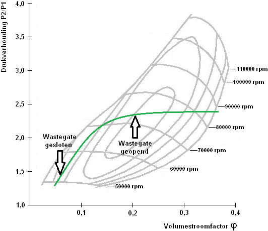
The image shows the compressor map of a turbo on an engine operating at part load. At part load, the aim is the lowest possible specific fuel consumption. This lowest specific fuel consumption occurs at operating points that are near the compressor’s most efficient area. This area is shown by the smallest efficiency islands on the compressor map.
The engine control system controls the boost pressure in such a way that the compressor operating point is in a favorable efficiency region. In the image this is indicated by the green line: it shows how the compressor operating point changes as air demand increases.
At the beginning of the line, the wastegate is closed. As a result, all exhaust gas flows through the turbine wheel and boost pressure increases. As the desired boost pressure is reached, the engine management system partially opens the wastegate to route some of the exhaust gases around the turbine, preventing the boost pressure from increasing further. The turbo shaft speed in this operating range lies between about 80,000 and 90,000 revolutions per minute, as can be read from the speed lines on the compressor map.
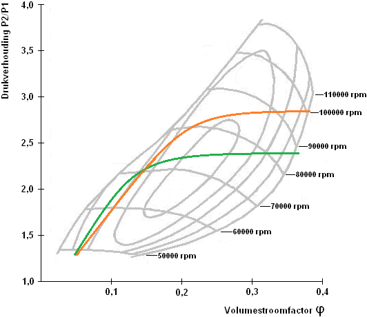
When driving in the mountains, there is a higher geographical altitude where air pressure is lower and the air is thinner. This affects the operation of the turbo because the pressure upstream of the compressor decreases. As a result, the intake air contains less oxygen per unit volume. To still achieve the same absolute boost pressure in the intake manifold, the compressor must deliver a higher pressure ratio. This means that both the pressure ratio P2/P1 and the compressor speed must increase. This situation is shown in the image.
The green line shows the part-load situation when driving at sea level. The orange line shows the part-load situation when driving in the mountains. Due to the lower air pressure at altitude, the compressor operating point shifts to a higher pressure ratio and a higher speed. In this example, compressor speed increases to about 100,000 revolutions per minute.
Because of the higher compressor speed, the temperature of the compressed intake air fed to the engine also rises. The intercooler must therefore remove more heat to limit intake air temperature. In addition, a difference in fuel consumption is visible. When driving in the mountains, fuel consumption increases. This is caused by the higher pressure ratio P2/P1, the higher turbo speed, and the lower overall efficiency of the compressor under this operating condition.
Combination of turbo and supercharger:
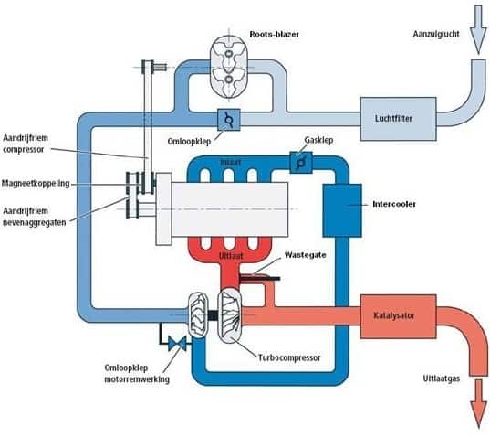
More and more often, car manufacturers choose to equip an engine with both a turbo and a mechanical supercharger. The turbo is often larger in size and is equipped with a wastegate. The supercharger is used to reduce or prevent turbo lag. At low engine speeds, the supercharger provides boost pressure directly and helps the turbo get going faster. At higher engine speeds, the turbo takes over boost pressure entirely and the supercharger is switched off or bypassed.
The intake air is first compressed by the supercharger. Depending on the operating situation, the air flows via a bypass valve directly to the turbo or the supercharger is bypassed. Then the air is further compressed by the turbo, cooled in the intercooler, and then routed to the intake manifold. Click here for more information about the Roots supercharger.
Electronic turbo:
A conventional exhaust-gas turbo suffers from turbo lag at low engine speeds because sufficient exhaust-gas energy is needed to drive the turbine wheel. A mechanical supercharger does not have this disadvantage and can deliver boost pressure starting from idle speed. A combination of both systems therefore seems ideal. However, a mechanical Roots supercharger must be driven by the crankshaft, which costs extra engine power and reduces efficiency.
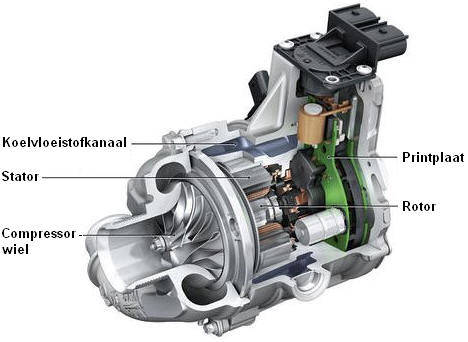
To reduce turbo lag without additional mechanical losses, car manufacturers are experimenting with electric turbos or combinations of multiple turbos. In an electric turbo, the compressor wheel is driven by an electric motor instead of by exhaust gases. The electric turbo is controlled by the ECU. Within about 250 milliseconds, the compressor wheel can reach a speed of around 70,000 revolutions per minute. This allows boost pressure to be built up immediately at low engine speeds. The compressed intake air is then routed to the compressor of the exhaust-gas turbo.
As soon as enough exhaust-gas energy is available, the exhaust-gas turbo takes over pressure build-up and the electric turbo is switched off or becomes less active. In this way, turbo lag is greatly reduced while avoiding the energy loss of a mechanically driven supercharger. By using an electric turbo, the engine responds faster to the accelerator pedal. At higher engine speeds, where the exhaust-gas turbo can independently deliver full boost pressure, the electric turbo is switched off completely.