Introduction to Towed Vehicle Brakes:
The brake system of a truck with a trailer has an extensive braking system to control the trailer’s brakes. The regulation of the braking force is done through the towed vehicle control valve (ECE valve). The trailer’s airlines are connected to the tractor’s coupling heads with pneumatic couplings. The colors of these coupling heads indicate different functions:
- Red coupling head: Supply line. This line supplies air pressure to the trailer’s tanks via the engine’s air compressor.
- Yellow coupling head: Control line. This transmits the brake command from the tractor’s control valve to the trailer’s relay valve.
The image below shows the structure of the air brake system as depicted on the service brake and parking brake pages, with the addition of the towed vehicle control valve (15) and coupling heads (16). This page does not further discuss the truck’s air supply and consumption systems, as these are considered known.
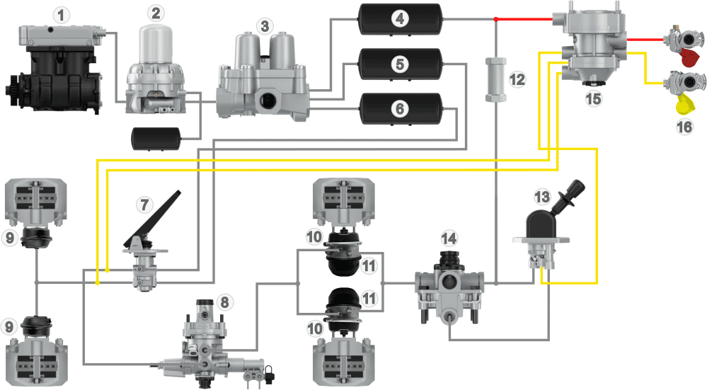
Legend:
1. Air Compressor
2. Dryer with Wet Tank
3. Four-Circuit Protection Valve
4. Air Tank Circuit 3
5. Air Tank Circuit 1
6. Air Tank Circuit 2
7. Foot Brake Valve
8. Load-Sensing Valve (ALR)
9. Diaphragm Cylinders (Front)
10. Diaphragm Cylinders (Rear)
11. Spring Brake Cylinders (Rear)
12. Check Valve
13. Parking Brake Valve
14. Relay Valve
15. Towed Vehicle Control Valve
16. Coupling Heads
- Red: Supply
- Yellow: Control
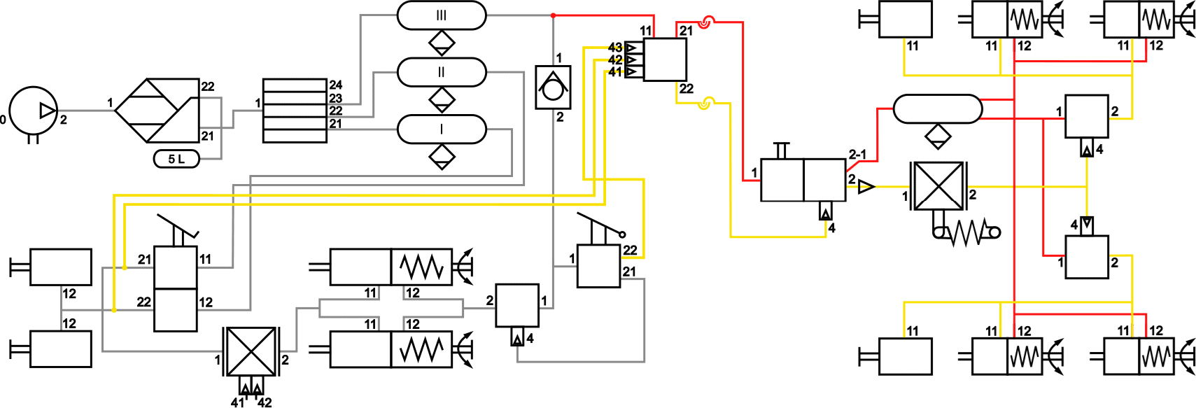
The following diagram also includes the towed vehicle control valve and coupling heads. Unlike the diagram on the “emergency and parking brake” page, the parking brake valve has an additional outlet: 22. This connection is linked to inlet 43 of the ECE valve.
The trailer’s air tanks are filled from air tank III and the red supply line (11 and 12 on the ECE valve). The foot brake valve activates both the front and rear brakes of the truck, as well as the ECE valve on connections 41 and 42.
Connections 21 and 22 on the towed vehicle control valve are linked to the red and yellow air coupling heads or a duo-matic coupling. Using coiled air hoses, the driver can connect the air couplings between the truck and trailer.
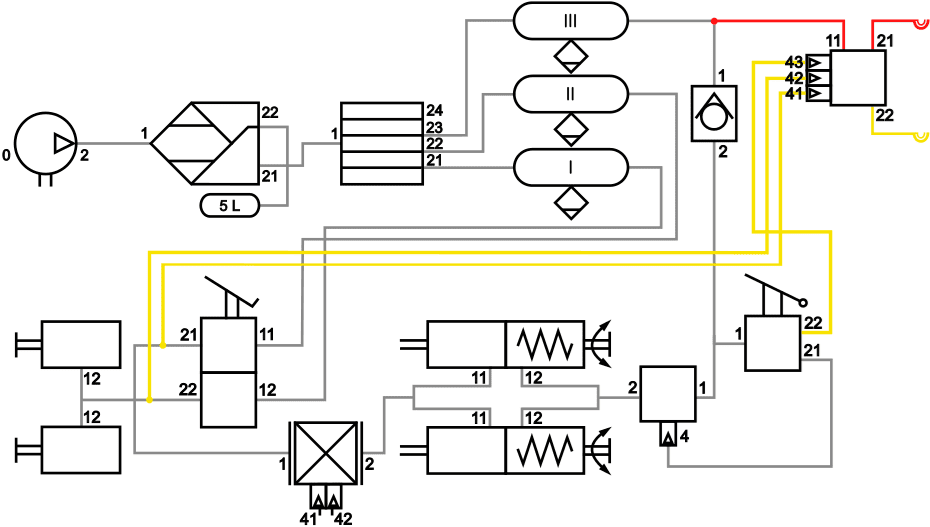
Codings on the ECE Valve:
11: Supply Ingress
21: Supply Outlet
22: Control Outlet
41: Circuit 1 Ingress
42: Circuit 2 Ingress
43: Circuit 3 Ingress
- Red: Supply
- Yellow: Control
On the trailer side, we also find air coupling heads where the coiled air hoses are connected. The yellow (control line) and red (supply line) enter the towed vehicle relay valve (3). The supply air is directly routed to air tank (4). Once sufficient pressure is reached, the relay valves (6) and spring brake boosters (8) are supplied with air. This releases the parking brake. See the “service brake” page for an explanation of the spring brake cylinders.
The mechanical ALR (5) is supplied with air from the control line. The braking pressure the driver applies to the foot brake valve determines the control pressure at the ALR. The end of the lever on the ALR is connected to the chassis. The more the chassis is loaded, the more the airbags or leaf springs are compressed. The mechanical ALR determines the command pressure transmitted to the relay valves (6) based on this load. A higher load means more braking pressure. The relay valves pass the supply pressure to the diaphragm cylinders to press the brake linings against the discs or drums according to the command pressure.
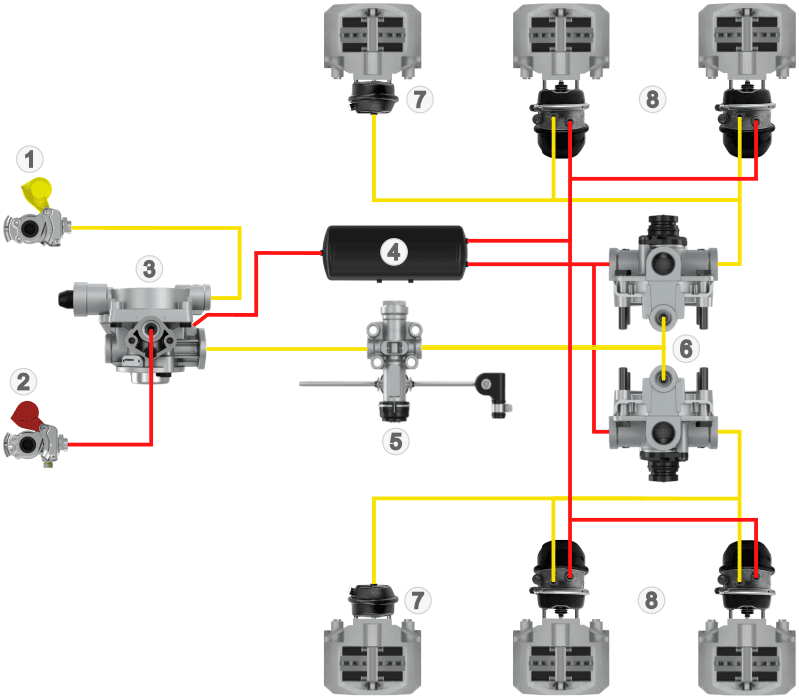
Legend:
1. Air Coupling Head Control
2. Air Coupling Head Supply
3. Towed Vehicle Relay Valve
4. Air Tank
5. Mechanical ALR
6. Relay Valves
7. Diaphragm Cylinder Service Brake
8. Diaphragm and Spring Brake Cylinder Service and Parking Brake
- Red: Supply
- Yellow: Control
The diagram below shows the symbols and codings of the components from the above illustration.
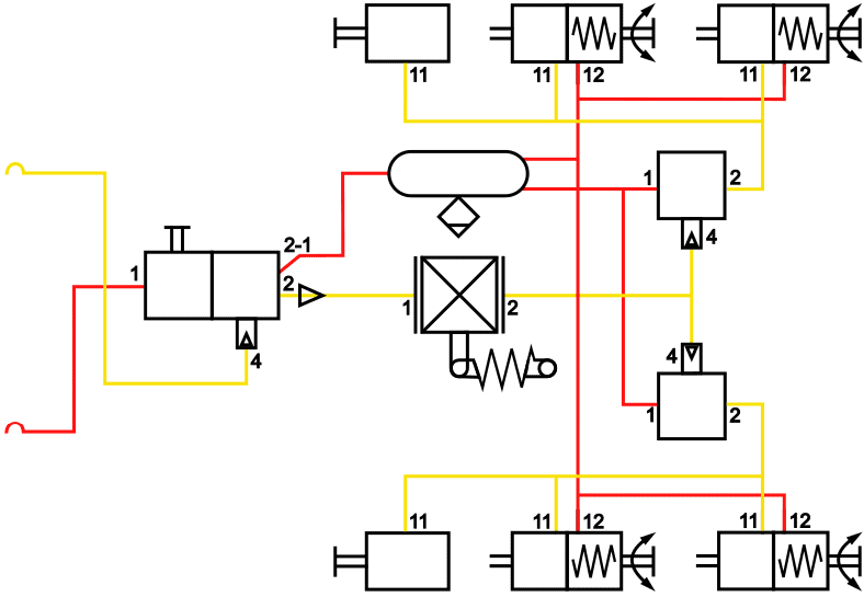
Legend of Codings:
1. Ingress
11. Ingress 1
12. Ingress 2
2. Outlet
21. Outlet 1
22. Outlet 2
4. Control
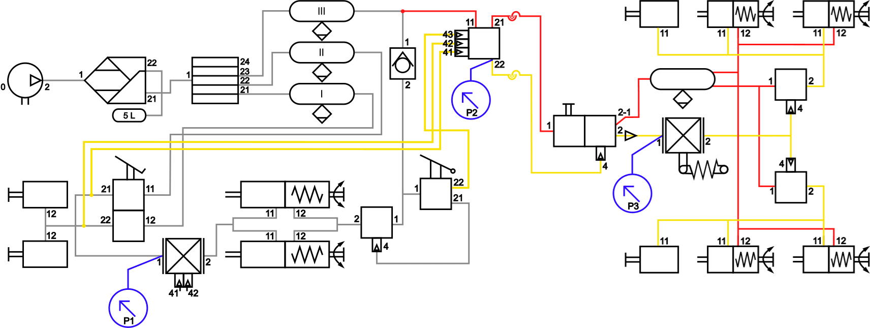
The diagram below shows the connected schematics of the motor vehicle and trailer.�a0
In the following sections, we delve deeper into the functioning of the parts related to the towed vehicle. Components of the towed vehicle corresponding to the motor vehicle (such as air tank, relay valve, and brake cylinders) will not be elaborated on here to avoid redundancy. For this information, refer to the pages: introduction, service brake, and auxiliary & parking brake of the truck.
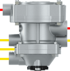
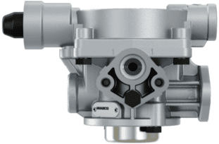
Towed Vehicle Control Valve (ECE Valve):
The towed vehicle control valve is also known as an ECE valve or ECE valve. This valve is located on the motor vehicle and regulates the brake pressure to the towed vehicle when the service brake or emergency and parking brake is activated. The towed vehicle control valve has an adjustment screw to set the lead control of the towed vehicle. More on that in a separate section.
The images alongside show the towed vehicle control valve and its symbol. The red lines (11 and 12) are the supply pressure inlet and outlet, and the yellow (22, 41, 42, 43) for the command pressure.
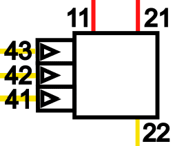
The towed vehicle control valve receives brake pressure from an air tank at connection 11. Connection 21 sends the supply pressure via the red hose to the towed vehicle. Connections 41, 42, and 43 come from the foot brake and hand brake valves. The pressure on these lines determines the level of the dispatched command pressure (22), which controls the towed vehicle’s brakes.�a0
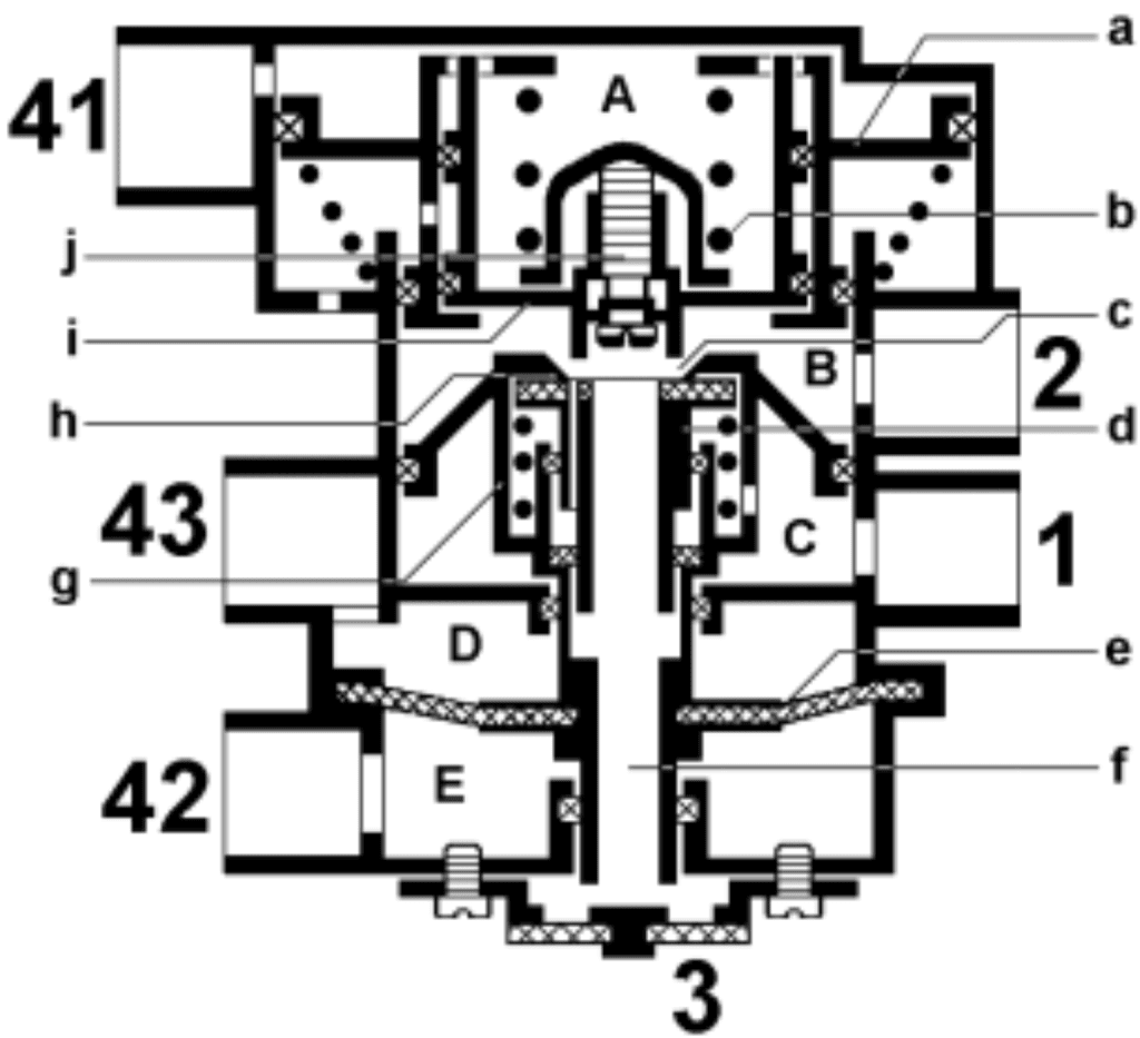
Brake Unapplied:
The supply pressure from circuit 3 enters at connection 1. Chamber B is not pressurized as bores b and h remain closed.
Partial Braking:
When the driver brakes, the brake pressure from the foot brake valve enters connections 41 and 42. The air pressure from connection 41 pushes piston f downwards and eventually opens seat b. Air from chamber C flows into B and exits through connection 2 of the control valve towards the yellow control line. The pressure in chamber B increases the pressure below piston f, closing the pipe stand. There is now an equilibrium situation for partial braking.
Full Braking:
During hard (full) braking, the pressure on piston f is at maximum. The pipe stand is fully pressed down and lifted from its seat. Therefore, there is no longer an equilibrium situation. Connection 2 remains fully pressurized, and so the command pressure is also at its maximum.
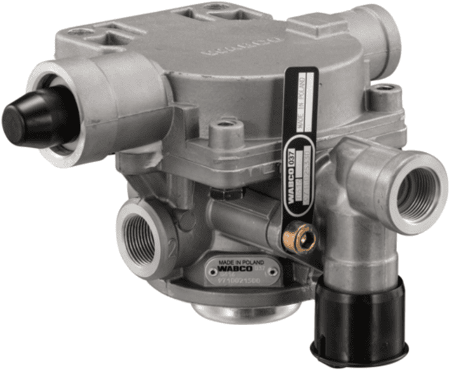
Towed Vehicle Relay Valve:
The towed vehicle relay valve is located on the trailer and has two functions:
- The valve operates the braking system of the towed vehicle when the truck’s brakes are activated. The brake pressure depends on the output pressure from the towed vehicle control valve.
- The valve also operates the braking system of the towed vehicle when the pressure in the supply line sharply drops due to a leak in a circuit.
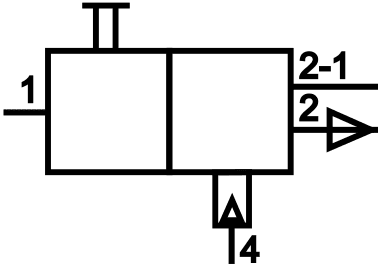
System Filling:
When connecting and coupling the trailer, air is supplied from the motor vehicle to inlet 1. When the air system of the trailer is still depressurized, air flows to connections 2-1 (to the tank) and 2 (to the ALR). Since there is also pressure on connection 2, the trailer’s service brake is simultaneously activated. The service brake remains active until a tank pressure of 3 bar is reached. This internally closes off the connection between inlets 1 (intake) and 2 (ALR and diaphragm cylinders). At that point, the service brake is released. Filling the air tank continues until a pressure of 8 bar is reached.
Braking:
During partial braking, command pressure from the towed vehicle control valve on the motor vehicle flows via the control line to connection 4 of the towed vehicle relay valve. The relay valve then allows air to flow from connection 1 to connection 2, causing the trailer to brake depending on the axle load measured by the ALR. The command pressure on connection 4 determines how hard the trailer brakes. In vehicles with EBS, the command pressure on connection 4 is blocked by a solenoid, and the command pressure is measured by a pressure sensor. This pressure level is sent to the EBS control unit (trailer modulator) for further processing.�a0
Hose Break Protection and Breakaway Braking System:
The towed vehicle relay valve contains hose break protection, ensuring that the trailer fully brakes when the trailer breaks away from the motor vehicle. If the supply line is disconnected or breaks, the ALR causes the relay valves to fully open, allowing tank pressure to flow to the brake cylinders. To release the brakes again, the brakes can be released via the release valve on the towed vehicle relay valve.
The diagrams below show a towed vehicle relay valve with a corresponding Wabco schematic.
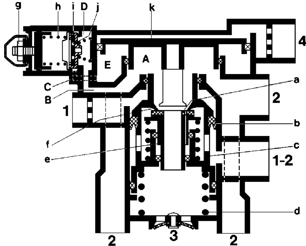
Lead Control:
In a motor vehicle and trailer combination, it is important for both to brake equally hard. If either the motor vehicle or the trailer brakes too hard, it can lead to dangerous situations (such as jackknifing) or increased wear on brake components or couplings like the fifth wheel or kingpin of a trailer, or drawbar eye and drawbar of a steered trailer. With lead control, the braking deceleration of the motor vehicle and trailer can be aligned. When both the motor vehicle and trailer brake equally hard, it is referred to as “harmonization.”
Lead control can be adjusted on the towed vehicle control valve by slightly increasing the dispatched command pressure. The pressure flows faster through the line, compensating for flow losses in the control line and hoses between the towed vehicle control valve on the motor vehicle and the trailer’s brake cylinders.
The lead control can be adjusted by turning bolt j (see image alongside). This changes the pre-tension of spring b. By adjusting this spring tension, the required pressure to push piston a against the command pressure from connection 41 changes. The pressure increase is infinitely adjustable between 0.2 and 1.0 bar lead control.
Lead control can be adjusted by measuring the pressures. It is not intended to adjust this screw without measurements, as it influences the brake balance between the motor vehicle and trailer.
The lead control of the towed vehicle control and relay valve can be determined by measuring the incoming and outgoing pressures with manometers. Consult the workshop documentation for the prescribed pressures.
We want to measure the pressure at connection 41 of the towed vehicle control valve. As there is no measurement connection here, another point must be found in the schematic. This is at inlet (1) of the motor vehicle’s pneumatic ALR. Manometer 1 is connected here to read pressure p1.
Pressure gauge 2 is connected to the control line after the towed vehicle relay valve. The pressure difference between p1 and p2 is the lead control of the trailer. For a good overview, pressure gauge p3 can be connected to inlet 1 of the ALR on the trailer, but it is not necessary for measuring the lead control.
Example of Lead Control Measurement Results:
- Input pressure p1: 2.0 bar
- Output pressure p2: 2.5 bar
- Lead control: 2.5 – 2.0 bar = 0.5 bar
If the manufacturer specifies that the lead control should be 0.3 bar, the adjustment screw on the ECE valve can be adjusted so that in a subsequent measurement, the output pressure will be 2.2 bar, resulting in a lead control of (2.5 – 2.2) = 0.3 bar.
Related Page: