Tow Hitch:
The tow hitch is usually installed on the vehicle afterward. Often, a choice can be made between:
- A fixed ball tow hitch
- A detachable ball tow hitch
- An electrically retractable tow hitch
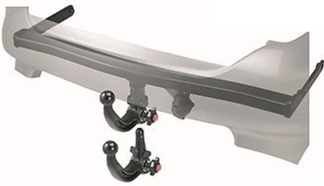
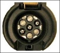
The tow hitch with a detachable ball is the most commonly installed (see image). The tow hitch itself is often U-shaped and screwed into the car’s cross members at both ends. In other vehicles, it may be a metal bar mounted only at the rear of the cross members.
The installation of the tow hitch is often quite simple. When the rear bumper is removed (and often the rear light units as well), the steel bumper bar can be removed. The tow hitch replaces this. It must then be attached to the chassis with 4 or 6 bolts (consult the manufacturer for the correct torque settings, as this is very important!) Be aware that there are vehicles where you must drill holes in the chassis parts!
There must be enough space left for the tow ball, the possible knob for mounting/dismounting, and of course, the socket. This must also be accessible. Connecting the wiring is often more challenging. This is explained in the next chapter.
Wiring:
When purchasing a tow hitch, a choice can be made between a 7-pin or a 13-pin socket. The difference is that the 13-pin has a constant and a switched live, which is necessary to operate, for example, the refrigerator and interior lighting in a caravan. This is extensively described (with pin assignments and colors) on the terminal codes page (socket).
The images below provide insight into how the wiring runs from the standard 7-pin, the standard 13-pin, or the 13-pin CAN-bus tow hitch wiring.
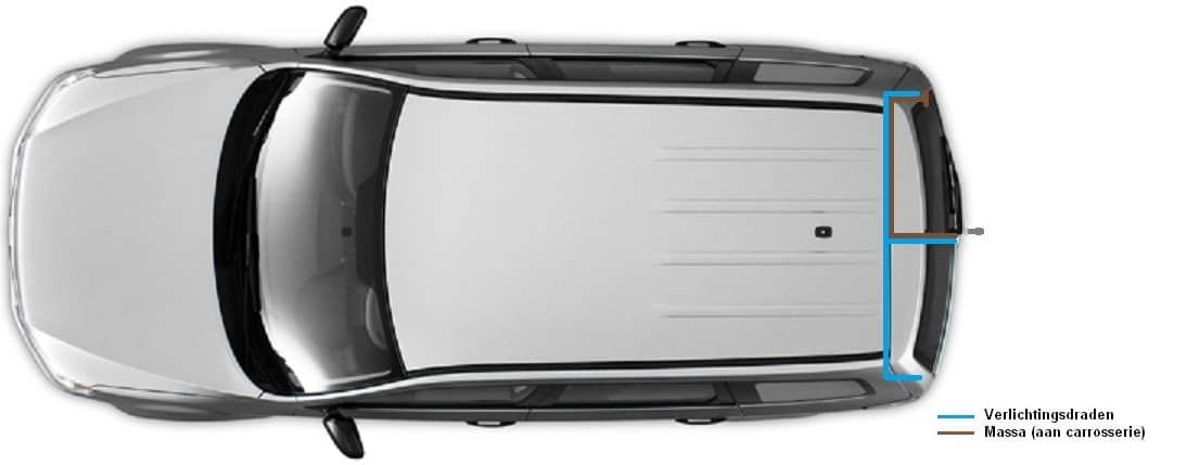
7-pin Socket (Standard):
From the socket, a wiring harness runs directly to the taillights. This is the simplest version. Often, they are plug-and-play sets made specifically for a type of car, allowing the taillight connectors to be plugged into the wiring set. The connectors of the wiring set should then be mounted on the taillights. This way, the wiring does not need modification as only connectors are clicked together correctly. This wiring can be installed very quickly and easily.
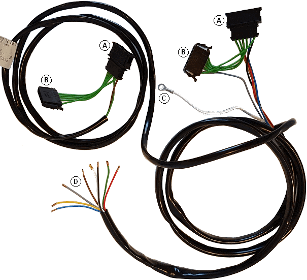
An example of such a standardized wiring harness can be seen in the image below.
The image shows the wiring harness of a Volkswagen Polo 9N. This harness is installed between the standard connectors and the taillights. Since the harness is specifically designed for this Polo, all cables are the correct length, and the wires are in the correct positions within the connectors. Below is an explanation of what the designations A through D represent:
- A: This is where the taillight connectors are clicked in.
- B: These connectors are clicked into the taillights.
- C: This is the ground cable and should be mounted to a ground point on the chassis.
- D: These eight cables are for the 7-pin socket. One wire functions to switch off the car’s rear fog light when the socket lid is opened. Voltages are looped from connector A to both connector B (to the taillights) and the wires to the socket (D). With this harness, there is no constant or switched live. For this, a 13-pin socket must be installed, and two wires must be run to the front of the car to connect them to the fuse box.
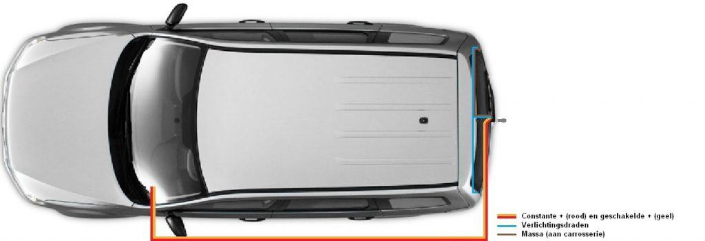
13-pin Socket (without CAN-bus):
From the socket, cables run to the taillights (as with the 7-pin). The taillights directly control trailer lighting. In a 13-pin socket, there is also a constant and a switched live present. These are connected to 12 volts via the fuse box (under the dashboard or otherwise under the hood). The constant live always has power, and the switched live only gets power when the ignition is on (position 15, or when the engine is running).
The wiring naturally runs inside the vehicle (above the threshold) but can also run forward via the right side. This depends on the vehicle type. In some cars, the wiring also runs under the car from the back to the front.
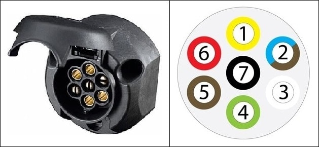
| 1. | L | Left Turn Signal | Yellow |
| 2. | 54G | Rear Fog Light (formerly constant live) | Brown / Blue |
| 3. | 31 | Ground | White |
| 4. | R | Right Turn Signal | Green |
| 5. | 58R | Tail Light, Right Side Marker, License Plate Light | Brown |
| 6. | 54 | Brake Lights | Red |
| 7. | 58L | Tail Light, Left Side Marker | Black |
Note! The pin assignments are standardized in the socket. The wire colors can vary by manufacturer. Please check the appropriate installation instructions or factory data!
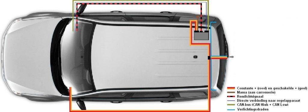
13-pin Socket (with CAN-bus):
The CAN-bus version uses a control module. This control module manages the lighting (except for the brake lights) on the trailer. From the BCM (Body Control Module, every manufacturer may use a different name), CAN-bus wires run to the tow hitch control module. Via these CAN-bus wires, information is transmitted on which lights should be on. An extra feature of this CAN-bus system is that it detects when a light is defective on the trailer. A notification will be given to the driver. The trailer control module constantly checks this as is the norm nowadays in the car when there is defective lighting.
The brake lights are separately controlled so that when there is a CAN-bus failure with the trailer control module, the brake lights will still function. Also, the constant and switched live wires are present for the socket. These also serve as power supply for the trailer control module.
The trailer control module must always be coded using branded diagnostic equipment.
The 13-pin socket can be either a Jaeger (the most common) or a Multicon. The Multicon West is a combination of a 7-pin and a 13-pin socket. A 7-pin plug from a trailer can be easily connected to it. Only the large, inner contacts are used in this case (numbers 1 to 7). The outer contacts remain unused. A conversion plug is not required. The outer contacts are only used when a 13-pin plug of the same type is connected.
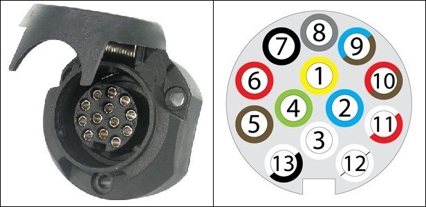
| 1. | L | Left Turn Signal | Yellow |
| 2. | 54G | Rear Fog Light (formerly constant live) | Blue |
| 3. | 31 | Ground | White |
| 4. | R | Right Turn Signal | Green |
| 5. | 58R | Tail Light, Right Side Marker, License Plate Light | Brown |
| 6. | 54 | Brake Lights | Red |
| 7. | 58L | Tail Light, Left Side Marker | Black |
| 8. | 8 | Reverse Light | Gray |
| 9. | 9 | Constant Live (e.g., for interior lighting) | Brown/Blue |
| 10. | 10 | Switched Live (e.g., battery or caravan refrigerator) | Brown/Red |
| 11. | 11 | Empty Position (optional ground) | White/Red |
| 12. | 12 | Empty Position | – |
| 13. | 13 | Ground | Black/White |
Note! The pin assignments are standardized in the socket. The wire colors can vary by manufacturer. Please check the appropriate installation instructions or factory data!
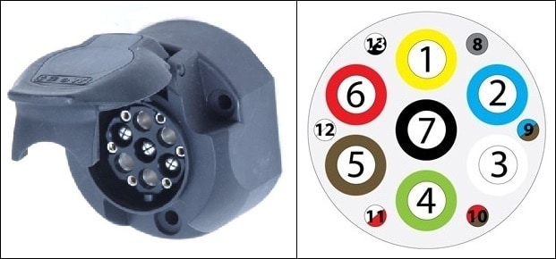
Multicon Feder:
The Multicon Feder is the predecessor of the Multicon West. The difference lies in the outer pin configurations; 8 through 13. In the Multicon Feder (see image), these are flat contacts, whereas, in the Multicon West, they are round pins.
The ‘Feder’ connection is no longer used today because it is more prone to malfunctions than the ‘West’. Also, with this socket, a 7-pin plug can be connected for a simple trailer or a bike rack.
Safety Cable and Breakaway Brake System:
To adequately secure a trailer to the vehicle, it is legally required to use a safety cable or breakaway brake system. If the trailer detaches from the tow hitch during driving due to equipment failure or improper operation, a safety system must be present to activate.
For trailers with a maximum mass (of the trailer including load) up to 1500kg, a safety cable is sufficient. A safety cable is nothing more than a thick steel cable attached to the trailer on one end and to the vehicle on the other. If the trailer detaches from the tow hitch during driving, the cable ensures the trailer continues to follow the vehicle. The safety cable does not engage the trailer brake.
When the trailer’s maximum mass exceeds 1500kg, it must be equipped with a breakaway brake system. The breakaway brake consists of a steel cable that pulls the trailer’s handbrake when it detaches during driving. The cable must be thinner than a safety cable; it needs to break after the handbrake is applied at a specified tension. The trailer then brakes independently without being connected to the vehicle. Having both a safety cable and a breakaway brake system on one trailer is not allowed. In an emergency, the trailer’s wheels might lock due to the breakaway brake system, while still being towed by the safety cable.
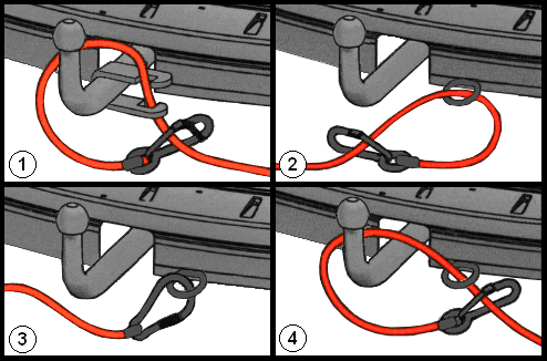
The images on the right display four ways to attach the safety cable and the breakaway brake system. The cable must always be connected to a fixed part of the tow hitch or the vehicle’s chassis. In image 1, a special bracket is mounted on the tow hitch. The cable must be looped through the bracket.
In images 2, 3, and 4, the cable is attached to a fixed point of the vehicle’s chassis. This fixed point can also be a hole in the tow hitch bracket where the ball is mounted. An extra loop can also be placed around the tow ball, as seen in image 4. It is prohibited to lay the cable directly over the tow ball as a loop without it being attached to a fixed part of the tow hitch or the chassis. The current fine for this mistake is more than 150 euros.
In vehicles with an (electronically) retractable tow hitch, it is often not possible to mount a bracket as shown in image 1 above. The tow ball is often shaped differently; usually square or rectangular. There may be an eye on the ball itself where the cable can be mounted, although experience shows this is not always the case. The manufacturer, and therefore also the dealer, can supply adapters that fit the corresponding tow ball. Consult your brand dealer for this.
Ensure that during the mounting of the cable, it does not touch the ground during driving, even when the vehicle will bounce at the rear. Damage to the cable results in an unreliable safety system.