Introduction:
Parking assistance includes systems that assist a driver in parking and exiting a space. The most well-known parking assistance system is “park distance control,” abbreviated as PDC. This system informs the driver of the vehicle about the distance to the car behind, or in more advanced systems, also to the front of the vehicle. This page describes modern technologies that either extend park distance control or are standalone assistance systems.
Park distance control:
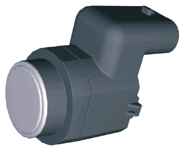
Park Distance Control (PDC) is a distance warning system that measures and informs about the distance to an obstacle during parking. Ultrasonic sensors are located in the rear bumper and often in the front bumper as well (see image). These emit sound waves at a very high frequency that are inaudible to human ears. These ultrasonic frequencies bounce off nearby objects and are received by the sensor again. The sensor measures the time between sending and receiving these signals. The closer the object is, the faster the signal bounces back. The sensor picks it up and relays the information to the PDC control unit (computer).
This computer can alert the driver with sound signals or both visual and sound signals. An audible beeping sound is heard, which beeps faster as the object gets closer. At a distance of about 30 cm, it emits a continuous tone, indicating to the driver to stop.
Modern onboard computers are often equipped with an option to display the distance to the object on a screen. The PDC sensors remain the same; the control unit calculates the data from the sensors and processes this into information the screen can display.
The image below shows the PDC control unit (ECU). Inside this gray square are the microcontroller, amplifier, and an AND-gate. The microcontroller sends a block voltage with a frequency of approximately 40 kHz (black). Additionally, a block voltage with a low frequency is periodically sent out (red/blue). The AND-gate receives the two block voltages. When both voltages are high, the output voltage (to the right of the AND-gate) is high. When one of the two voltages is low, the output is also low. The output voltage is returned to the microcontroller and sent to the transmitter in the PDC sensor. The transmitter emits the ultrasonic signal at a speed of approximately 300 m/s. When an object is nearby, the ultrasonic sound reflects and is registered by the receiver. This is referred to as “triangulation.” The receiver sends the formed block signal to the ECU. With the help of an amplifier, the block signal is strengthened for further processing by the microcontroller.
The time between receiving the output signal from the AND-gate and the amplifier indicates the distance to the object. The shorter the distance between the PDC sensor and the object, the shorter the time. The microcontroller activates the buzzer or communicates via the CAN-bus with other control units.
The circuit diagram below (VAG) shows the communication between the control units, inputs from switches, and outputs to, among others, the buzzer.
The PDC control unit (J446) receives the driving speed and reverse signal via the CAN-bus. Through connection T12/11, the PDC control unit sends a modulated block voltage to the wiring harness (X86 in the rear bumper) that connects to all PDC sensors (G203, G334, G335, and G206). Each PDC sensor has its own signal wire (via pin 2) to the ECU. Furthermore, the ground of each sensor is connected to a ground connection (352).
When one or more sensors detect an object, the control unit activates the buzzer (H15). Depending on the distance to the object, the buzzer emits a faster or slower intermittent sound signal.
Thanks to communication with the diagnostic interface (J533), it is possible to perform the following diagnostic functions:
- query error memory
- adjust codings of the control unit (e.g., after expanding the system with PDC sensors at the front or after installing a tow bar)
- adjust the buzzer volume
- query measuring value blocks of, among others, the distance of all sensors to the object, the calculated distance, and the stabilization time of the transmitter and receiver.
Backup camera:
In addition to park distance control, the parking assistant can also be equipped with a backup camera. When the driver shifts the vehicle into reverse or presses a button in the interior, the camera at the rear of the vehicle is activated. Usually, the display of the radio or onboard computer shows the image.
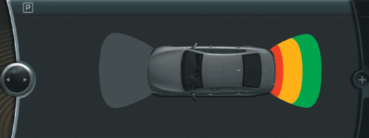
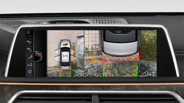
The image below shows a BMW display with the rear view of the vehicle. To the right of the camera image is a vehicle with a three-part grid at the front and rear; this displays the distance to an object registered by the PDC sensors.
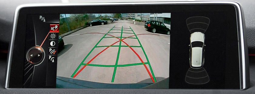
The image from the backup camera shows red and green lines. The red lines indicate the possible direction the vehicle can be steered; at maximum steering, the wheels on the outside of the turn will follow the red line. The green grid follows the direction in which the steering wheel is turned; currently, the front wheels are straight. When the driver turns the steering wheel, the green lines indicate the actual driving paths. The steering angle sensor records the position of the steering wheel.
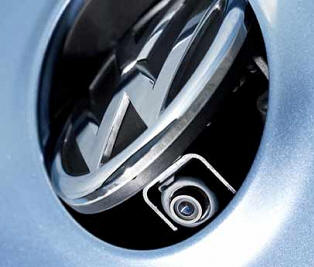
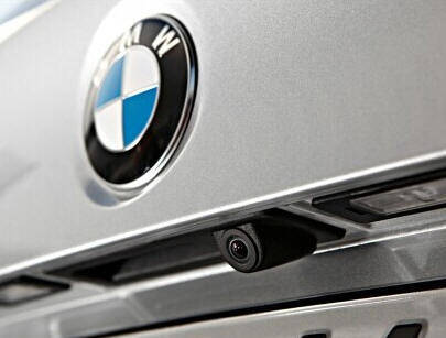
The backup camera is sometimes visible, often located near the license plate and/or the handle to open the tailgate. Manufacturers sometimes choose to mount the camera out of sight. The image below shows the backup camera of a VW Golf, where an electric motor tilts the VW emblem to move the camera outward. The emblem automatically retracts when driving forward again. Not only is the camera placed out of sight, but the lens also gets dirty less quickly.
Side view:
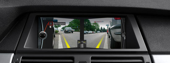
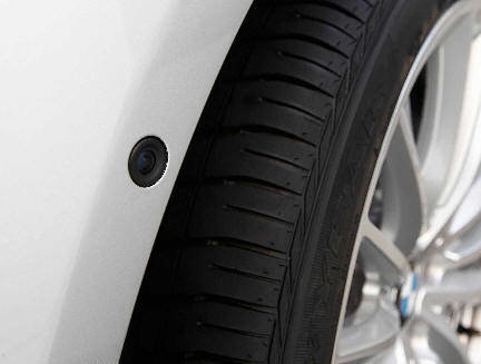
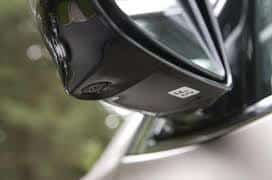
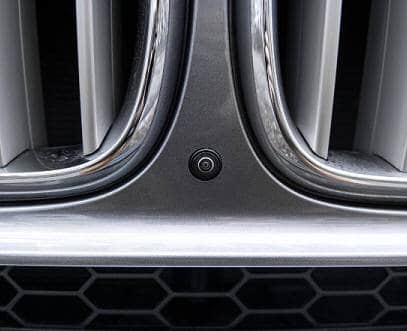
When parked backward between two vehicles or large objects, you need to drive slightly forward to look left and right. With a side view camera (also called corner view), this becomes much easier; cameras on the left and right in the front bumper send the image to the display in the dashboard. The image shows the view from the corner cameras. Cameras unfortunately cannot be mounted invisibly. Cars equipped with a side view camera typically have a (usually) black lens in the bumper. The image below shows the front bumper of a BMW with the left camera.
Surround view:
Among the most luxurious parking assistance systems is undoubtedly the “surround view,” also known as top view, 3D, or bird-view. Each brand gives its own name and characteristic to the system. We will use the term surround view now.
In surround view, the top view of the car is shown on the display. It appears as though there is a camera on the roof of the car observing the surroundings. The car is a simulation, and the surroundings are assembled by multiple (usually four) cameras.
The next three images (from BMW) show the image the driver sees. During parking, the boundaries of the parking space and the objects, such as poles, etc., are clearly visible. During reversing, you can zoom in on the rear; plants are especially visible here. Conventional PDC sensors register the distance to the plants. The computer marks this distance with a red color.
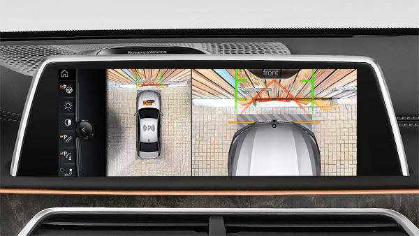
During forward parking, the system can also show the surroundings and the front. PDC sensors also help to determine the distance to the fence.
Parallel parking along a curb can cause damage to tires and rims if the driver isn’t careful. Here, too, surround view provides a solution; thanks to a good overview of the street view, you can park straight and close along the curb. BMW’s latest developments allow the camera image to be inverted and the vehicle to be simulated.

The next three images show where the cameras are usually located.
Parking exit assistance:
As an extension of parking assistance, so-called “parking exit assistance” can help the driver when reversing out of a parking spot with limited visibility. This can be in situations where the vehicle is parked next to a wall or between vehicles.
Sensors at the rear of the vehicle detect traffic passing behind and potentially posing a collision risk. This includes all moving objects approaching the vehicle at a certain speed. When the parking exit assistance system detects an approaching vehicle, a notification appears on the infotainment system display. An acoustic sound signal is usually added to this. If the driver ignores these signals and continues to reverse, the system physically intervenes by applying the brakes and slowing the vehicle down.
