Introduction:
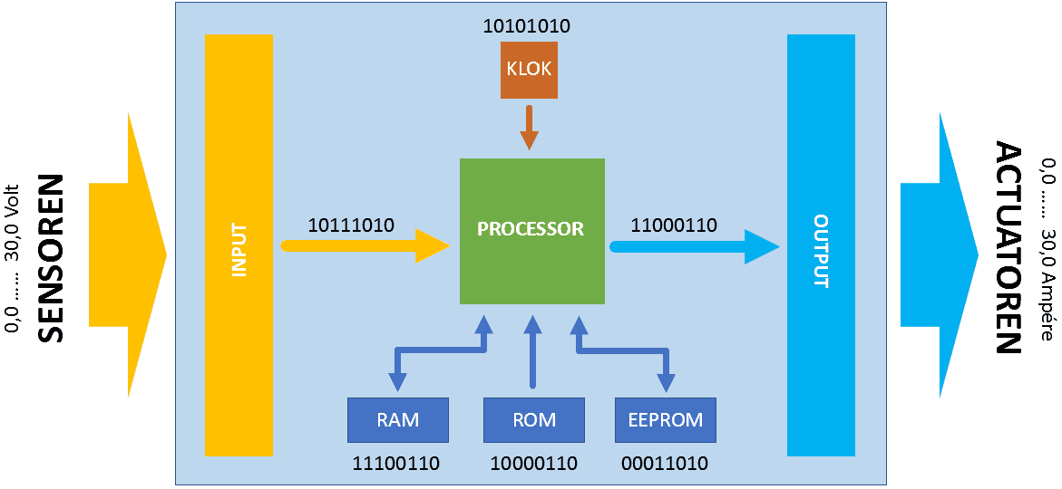
An ECU receives or measures data from sensors, processes the information, and performs calculations to control actuators. The image below shows a block diagram of a control system.
Sensors are transducers that respond to a physical quantity. The electronics in the sensor convert this into an electrical signal. The ECU receives this electrical signal as “input” and compares it to the preprogrammed value. Depending on the purpose of the signal, the actuator control is adjusted accordingly.
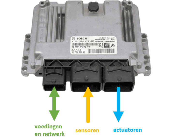
The following image shows an ECU with three plug connections. From left to right: power and network, sensors, actuators.
In a gasoline engine management system, we find, among others, the following sensors:
- crankshaft position sensor to measure the crankshaft speed;
- coolant temperature sensor to measure the heating of the coolant;
- throttle position sensors to measure the position of the throttle and thus the engine load;
- MAP sensor or airflow meter to measure vacuum or airflow;
- oxygen sensor to measure the oxygen content in the exhaust gases;
- the barometric sensor and intake air temperature sensors;
- knock sensor to advance the ignition as far as possible.
The sensors above serve as input to control the injectors and coil(s). Therefore, all sensor values are looked up in a preprogrammed map.
As an example, let’s consider injector control. At idle engine speed, the injectors spray in a certain number of degrees after TDC.
- At a low coolant temperature, the injection duration is extended (enriching);
- When accelerating gently, the injection duration is also extended. A measurement also takes place to monitor how quickly the throttle pedal is being pressed: when abruptly going full throttle, extra enrichment occurs;
- The vacuum in the intake manifold influences the injection timing and duration;
- The oxygen sensor (as an example, the jump sensor) measures whether the mixture is too rich or too lean. If the mixture is too lean for a number of crankshaft rotations, the injection duration is extended using the fuel trims, until the mixture is stoichiometric again;
- The barometric sensor and intake air temperature sensor measure the air pressure and temperature to determine the oxygen content in the intake air.
The injection duration thus depends on the values of no fewer than five sensors. In modern engines, even more sensors play a role.
During and after actuator control, the sensors feed information back to the ECU. The measured value is compared with the desired value in the software. This can determine whether actuator control can remain constant, needs to be shortened, or should be extended. The ECU thus acts as a controller, creating a control loop.
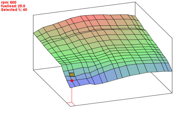
The next image shows a map in which the basic injection time is determined from the crankshaft speed relative to the vacuum in the intake manifold, which is a measure of engine load. The temperatures and oxygen sensor form a correction factor and each have their own map.
System Bus:
The system bus makes connections between the components in the ECU (see the image below). At the top of the ECU, we find the clock. This so-called oscillator provides a square wave frequency of usually 16 MHz. The clock frequency determines the speed of the control unit. The components in a control loop are synchronized by this timer.
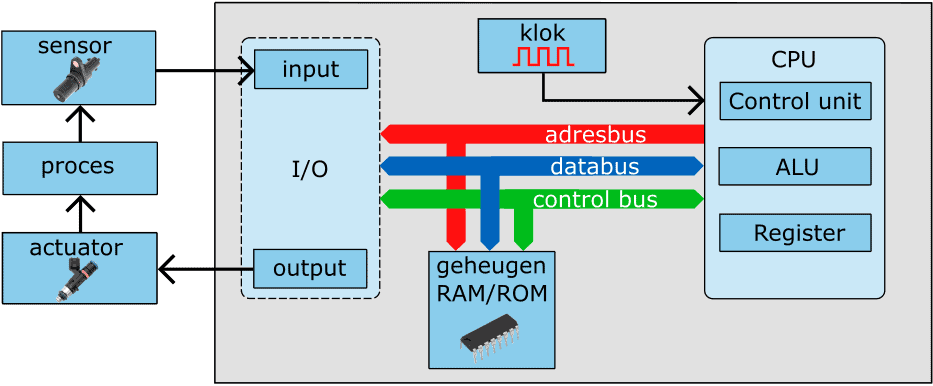
The CPU, memory, and I/O interface (I/O stands for: input/output) are interconnected with a system bus, consisting of multiple connections on the circuit board. These can be divided into:
- address bus: this bus ensures data transfer from the microprocessor to specific memory locations;
- data bus: data between memory, the CPU, and the interfaces is transported via the data bus;
- control bus: serves as control by performing read and write selections, requests, and resets based on the system clock timing.
Processor (CPU):
The processor (Central Processing Unit) forms the heart of the computer. The combinational circuits, which consist of a vast number of AND, OR, and NOT gates, are built in the ECU by software. During the manufacture of the processor, a number of instructions (the software) are embedded. These instructions perform operations and arrange them in the correct order. Example:
- the letters of the alphabet are digitally stored in the processor. In reality, it won’t be about letters, but digital instructions representing simple operations;
- by placing the letters in the correct order, we can form words;
- by placing the words in the correct order, we can form sentences;
- the sentences create the story: in reality, the computer program.
The program to arrange the – processor-known – instructions in the correct sequence is embedded in the software by the programmer. This program is loaded into the ECU’s flash memory.
When the ECU is started, the instructions are fetched one by one from the flash memory by the processor at the clock’s rate and executed. After the program is executed and completed, the cycle starts again.
The data required to load data such as ignition timings is loaded from the ROM memory. The processor boots from the ROM memory and copies data from ROM to RAM. After booting, the CPU fetches all data and commands from the fast RAM memory. A relatively small RAM memory is necessary for temporarily storing data and calculated intermediate values.
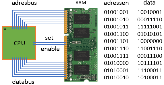
The CPU is connected to memory via an address bus and data bus.
- Set: bits are stored in the RAM
- Enable: bits are retrieved from the RAM
Bits and bytes of data in RAM memory can consist of:
- numbers: sensor data / data to actuators / calculations
- addresses of sensors (input) and actuators (output)
The data in RAM memory can include:
- letters: ASCII codes, numbers, letters, symbols
- instructions: processor instruction set (commands for processor)
The processor operates according to a so-called ISA (Instruction Set Architecture) or instruction set. The ISA is a list of instructions programmed by the manufacturer and used by the processor. The ISA differs per processor and is strongly dependent on the application for which the processor is used. Here are a few examples:
- LOAD the processor retrieves a value from the RAM memory
- STORE the processor stores a value in the RAM memory
- ADD the processor adds two numbers together
- CLR the processor clears a value in the RAM memory
- COMPARE the processor compares two numbers with each other
- JUMP IF the processor jumps to a certain memory address in RAM (condition from compare)
- OUT the processor sends information to an output
- IN the processor requests information from an input
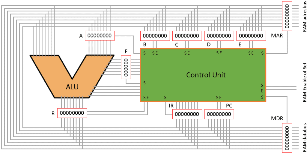
To allow a processor to operate at full clock speed, internal RAM memory is used. These are called “registers.” Registers are particularly important function blocks in many digital systems. They consist of an array of flip-flop circuits that can temporarily hold (thus remember) a binary number. The different types of registers are:
- A-register: register for A-input to ALU
- B-register: register for B-input to ALU
- Working register: general purpose, for storing (intermediate) results
- Instruction register: the current instruction to be executed by the processor is stored in this
- Address register (program counter): contains the address of the next instruction to be executed
- Flag register: number (after a calculation) is: zero, negative, positive, too large, even, or odd
- Floating Point Register: number with decimal places
- Shift register: memory where the data shifts one bit during each clock pulse
- Memory Data Register: buffer between CPU and RAM for memory data
- Memory Address Register: buffer between CPU and RAM for memory address
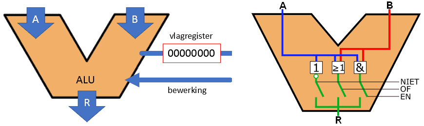
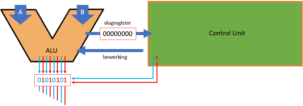
The ALU (Arithmetic Logic Unit) performs all arithmetic and logic operations (AND, OR, NOT, etc.).
- 2 inputs to ALU: A and B
- 1 input: which operation the ALU should perform
- 1 output: R (Result) goes to a register
- 1 output: flag register
1. The ALU wants to send 01010101
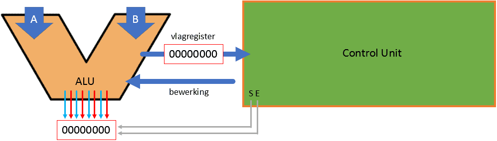
2. First, the Control Unit must make set “1”

3. The register is filled in
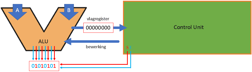
4. Then, Enable is made “1”.

5. The data from the ALU is placed on a bus
RAM memory:
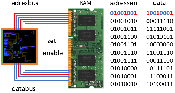
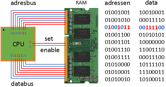
The CPU wants to fetch data from RAM memory. This happens in the following steps.
1. CPU sends an address to the RAM (01001001)
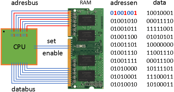
2. CPU wants to receive information; “enable” = 1
3. RAM sends data from address 01001001 to the CPU
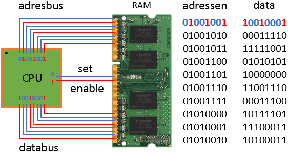
4. CPU processes the information
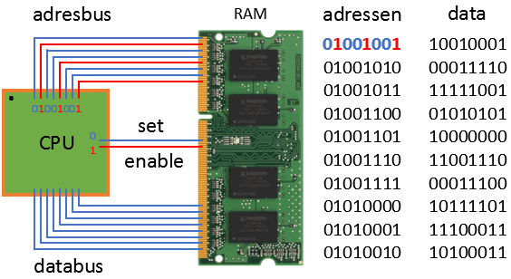
The CPU wants to store data in RAM memory:
1. CPU sends an address to the RAM (01001011)
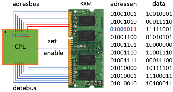
2. CPU wants to store information; “set” = 1
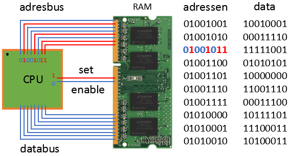
3. CPU sends data (00111100) to address 01001011 in the RAM.
The data in the RAM is now overwritten from: 11111001 to: 00111100
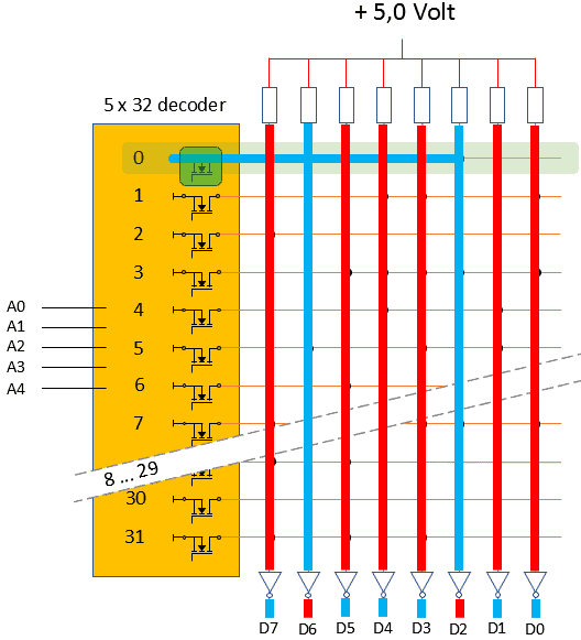
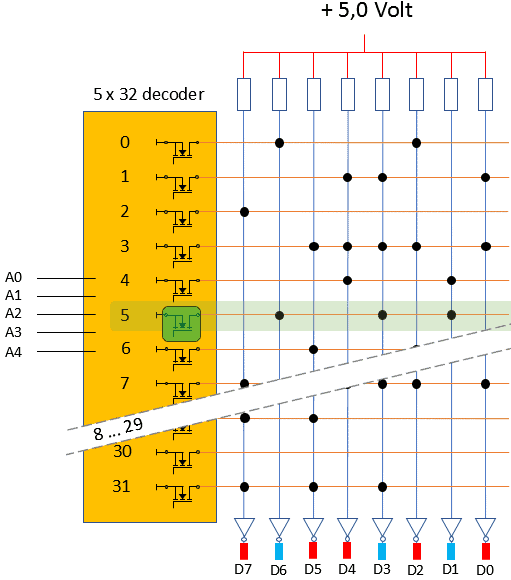
ROM memory:
ROM stands for: Read Only Memory. This memory is programmed by the manufacturer. The memory circuit is arranged with fixed connections. The ECU starts the software program (booting) from ROM memory. ROM memory is a slow memory. During booting, the data is copied from ROM to RAM.
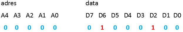
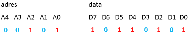
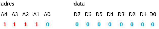
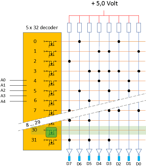
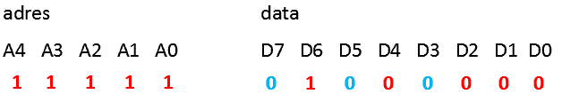
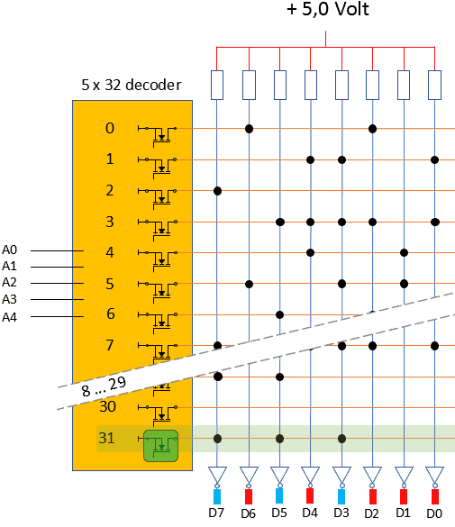
Below are four examples of reading the ROM.
Related pages: