Introduction to the MOST Bus:
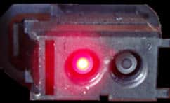
In audio systems, the MOST bus is increasingly used. MOST stands for: Media Oriented Systems Transport. The MOST bus is a ring-shaped network that utilizes light conduction. Each control unit in the network transmits optical signals using its own LED through a fiber optic cable. The frequency with which the LED flashes forms a signal that ultimately results in a message that can be received by other control units. In the image below, a connector is shown where a light signal is arriving.
The MOST bus is extremely fast due to a combination of LEDs and fiber optic cables. Both audio and video material can be sent and received via the MOST. Below is a MOST bus network used in the audio system of a car. The radio, display, amplifier, entertainment computer, DVD changer, and instrument cluster are included.
Via the entertainment computer, for example, a phone can be connected where music is streamed via Bluetooth. Music or movies can also be played via the DVD changer. The data is transmitted through the fiber optic cable to other control units in the network. The images will appear on the display, and the audio will be played over the speakers by the amplifier.
The data reaches the control unit, after which it is forwarded to the next control unit. When a single control unit is disconnected, the light beam will be interrupted, and no data transfer will be possible anymore.
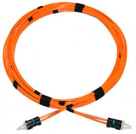
In the image on the right, a fiber optic cable is shown. Because the cable transmits light, it is important that the cable is not bent. If it is, for example, because the cable has become pinched behind the glove compartment, the light beam can be interrupted or weakened. Components in the MOST circuit will then no longer be properly controlled. The technician’s task is to localize the cause of the fault. This can involve a lot of diagnostic time.
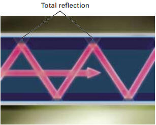
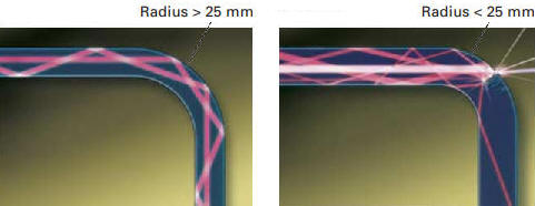
The light signals are reflected in the cable. If a too sharp bend is made, the signal in the cable can no longer be properly reflected. This is shown in the images below. When installing this optical cable, it should be placed in large loops where a bend needs to be made. The radius of the bend must exceed 25 mm.
Communication Protocols:
There are different generations of the MOST bus. The first generation was the MOST25, with a data speed of 25 Mbit/s. MOST50 (50 Mbit/s) was the successor of MOST25. The latest variant is the MOST150 (150 Mbit/s), where the data speed is 6 times higher than the first generation. Not only does the data speed differ per generation, but also the content and structure of the data frames. The differences are described in the following paragraphs.
MOST25:
In MOST25, the data speed is 25 Mbit/s (megabits per second). This means 25 x 1,000,000 bits, so 25,000,000 bits per second are transmitted. Another feature of MOST25 is that messages are sent in data blocks, each consisting of 16 frames. Each frame consists of 512 Bits (0 to 511). That equals 64 bytes. An example of a data block is shown in the image below.
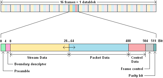
- Preamble: The preamble (which means opening or introduction) synchronizes the transceivers before the message.
- Boundary descriptor: Indicates how many of the available 60 bytes are divided into the synchronous and asynchronous bytes.
- Stream data: continuous data transfer (also called synchronous data) which requires high bandwidth. It is used for the continuous transfer of video and audio data.
- Packet data: data transfer through packets (also known as asynchronous data), where large data blocks are transmitted. These data blocks mainly consist of information for computing purposes and messages in the form of asynchronous data, such as GPS information. The packet data also requires high bandwidth.
- Control data: This data maintains communication between the various network ports.
- Frame control: Controls the respective data frame.
- : Parity bit: used to detect bit errors.
MOST50:
The MOST50 generation uses a data speed of 50 Mbit/sec. This is a doubling of the data speed of the MOST25. Not only is the data speed different from MOST25, but the length and structure of the frames are also different. A MOST50 frame consists of 128 Bytes, which is equal to 1024 Bits. This is also a doubling compared to MOST25.
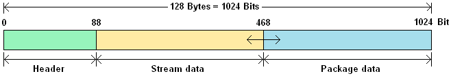
The layout of a data frame is also much simpler; a frame consists of:
- Header: Contains the administration, the boundary descriptor, 4 Bytes of Control Data.
- Stream data: same as MOST25.
- Package data: same as MOST25.
MOST150:
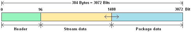
The MOST150 frames have a structure similar to those of MOST50 frames. The speed is 150 Mbit/sec, and contains 384 Bytes (3072 Bits) which is three times higher than the MOST50 frames.
Fault Localization:
When the MOST bus is interrupted, the light signal can no longer be transmitted to other control units. The result is a black screen, no sound, or other functions not working. This could be due to the following two causes:
- Fiber optic cable is interrupted.
- Control unit is defective.
A broken fiber optic cable can be caused by improper installation that pinches it (for example, behind interior parts such as the glove compartment), but also because it has been bent. The kink causes a weakening of the light signal. Therefore, the fiber optic cable should be checked for damage, kinks, or breakage. Since the fiber optic cable sometimes runs throughout the car, it can become an extensive search. Often a damaged fiber optic cable is the result of unskilled handling when installing a radio or dashboard parts. It is therefore advisable to start the search here.
If there is a light signal entering the control unit but not exiting it, the control unit may be defective. There may not be any faults stored in the fault memory. The location of the defect can be checked by excluding this control unit from the MOST circuit. An example of this is shown in the image below.
In this case, the DVD changer is no longer part of the MOST circuit. The fiber optic cables that were connected to the control unit are now connected together with a connector. The light signal is now transmitted from one cable to the other. If communication resumes in this situation, it may be that the DVD changer is interrupting the light signal. This can also be tried with other control units, as they are connected with similar types of connectors.
Faults can also be detected with diagnostic equipment. This is usually called a “ring break diagnosis.” More about this later…
The MOST bus is connected to the gateway. Communication can be established with other types of networks, such as the CAN or LIN bus, via the gateway.