Measuring radial crankshaft clearance:
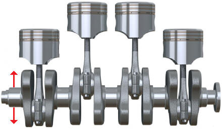
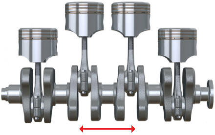
The radial clearance is the clearance of the crankshaft between the main bearings. There should always be a small clearance present because an oil film must be formed. The oil film fills the gap between the two moving parts. In the image below, the direction of the radial clearance is shown.
The radial clearance should obviously not be too small or too large. If the clearance is too small, friction can occur between the crankshaft and the plain bearings. If the clearance is too large, there is too much space between the crankshaft and the plain bearings. The consequences of incorrect clearance can include accelerated wear of the plain bearings. This will cause noise in the engine.
The clearance on the plain bearings of the crankshaft and connecting rods can be measured with Plastigage. Plastigage is a special plastic thread.
A bit of Plastigage should be placed on a clean surface. This could be a crankshaft bearing. Then the bearing cap should be mounted with the appropriate torque. The Plastigage now between the crankshaft bearing and the bearing cap will deform.
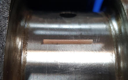
After the bolts of the bearing cap a0are a0tightened, they can be removed again. The imprint of the flattened Plastigage will now be on the bearing and the bearing cap (see images below).
Because the radial crankshaft clearance is different for each engine, Plastigage comes in three different sizes;
- Green: for bearing clearance from 0.025 to 0.076 mm.
- Red: 0.050 – 0.150 mm.
- Blue: 0.102 – 0.229 mm.
- Yellow: 0.23 – 0.51 mm.
The width of the flattened Plastigage indicates the clearance present between the crankshaft and the bearing cap. The thicker the line, the more the bearing cap is pressed against the crankshaft, so the smaller the clearance is. When the Plastigage is hardly deformed, the clearance will be very large.
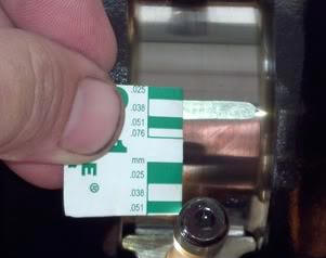
The packaging of the Plastigage shows a reference width with a size in millimeters or inches. By holding the card next to the flattened Plastigage, it’s possible to determine how many millimeters the clearance is.
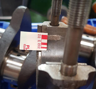
In the image above with the green card, the clearance is 0.038 mm. This clearance should be compared with factory data. Tolerances are often provided in this data. For the engine in this measurement, these tolerances are 0.030 – 0.050 mm. The measured value falls within the tolerances, so the clearance is okay. The same applies to the measurement with the red card, where the clearance is 0.51 mm. If the clearance were too large, thicker plain bearings could be chosen.
Measuring axial crankshaft clearance:
The axial crankshaft clearance is the clearance present in the lengthwise direction of the crankshaft. Operating the clutch exerts force in the longitudinal direction of the crankshaft. This is the axial direction. To absorb these axial forces, axial bearings are mounted on the crankshaft. In the image, the axial direction is indicated with arrows.
Measuring the axial crankshaft clearance can be done with a dial gauge. See the page Mechanical measuring instruments for more basic information about the dial gauge.
Step 1.
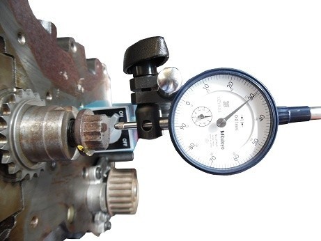
Mount the dial gauge on a fixed point on the engine block. In the image, the dial gauge is installed on the engine block. The tip does not yet touch the crankshaft bolt.
Step 2.
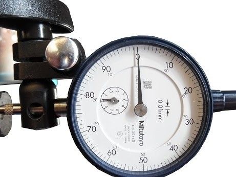
Set the dial gauge with a preload greater than 2 millimeters. This means that the probe of the dial gauge is pressed in by at least 2 mm while the crankshaft is not yet moved. If no preload is set, there is a chance that during the movement of the crankshaft, the probe will no longer touch the bolt. In the image, the preload is set to 5 mm (the small hand indicates the full millimeters).
Push the crankshaft (lengthwise) as much as possible to one side. Then turn the outer ring so that the zero on the dial is behind the hand.
Step 3.
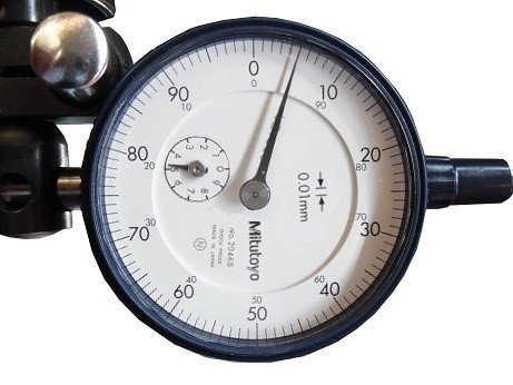
In the previous step, the hand was exactly at 0 with a preload of 5 mm while the crankshaft was moved to one side. With each movement made now, the needle will indicate more or fewer millimeters. The crankshaft should now be pushed in the axial direction to the other side. The hand will then indicate a different value from zero.
In the image, a clearance of 0.05 mm is indicated.
Consult the factory data of the respective engine to compare the measured value.