Introduction:
In automotive technology, Hall or magneto-resistive sensors are often used. These sensors are tasked with measuring the rotational speed and transmitting it to the respective control unit. This page describes the operation and applications of the Hall sensor.
Operating Principle of the Hall Sensor:
A Hall sensor works through magnetism. There are two types of Hall sensors, each with its own operation:
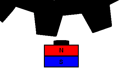
Hall sensor with permanent magnet:
By changing the air gap, an alternating magnetic field develops in the Hall sensor, which then generates alternating Hall voltage. This type of Hall sensor is often used as a speed sensor, for example, on the crankshaft gear. The crankshaft speed is transmitted to the ECU, which regulates the ignition, and to the instrument panel to control the tachometer.
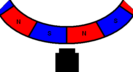
Hall unit with magnetic disc:
In this type of Hall sensor, a disc with magnets rotates past the mounted Hall unit. The rotation of the magnetic disc generates alternating Hall voltage. This type of Hall sensor is often used as an ABS speed sensor. Compared to the toothed ring system, this system has the significant advantage of operating at a lower speed. With the rotating magnetic disc, a well-recorded speed can already be detected at a slow-moving wheel (below 5 km/h), which was not possible with the toothed ring system.
The magnetic disc is integrated into the wheel bearing. These cannot be replaced separately.
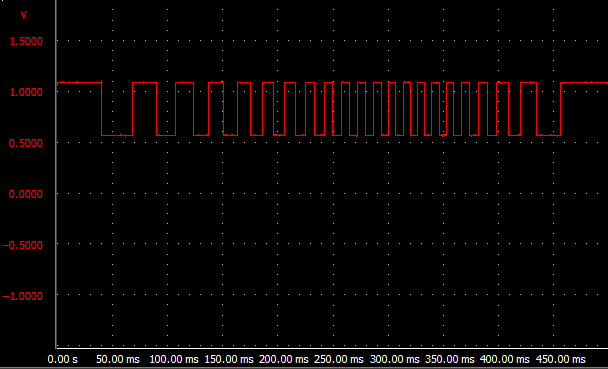
With an oscilloscope, the voltage trend of the Hall sensor can be displayed. Below is a scope image of an ABS sensor configured as a Hall sensor. The frequency changes as the wheel speed changes (the square wave becomes wider or narrower). The amplitude (the height of the signal) remains the same.