Introduction:
The information processing of modern motor vehicles is largely, if not entirely, digital. The digital information consists of electrical voltages, forming a yes/no or on/off signal based on the voltage level. In the interface electronics, there is an A/D converter (Analog / Digital) where a sensor voltage is converted into a digital message, consisting of ones and zeros.
In digital electronics, we speak of a logical 1 or a logical 0. The voltages are at TTL level (Transistor Transistor Logic).
- Yes or on: logical 1: 5 volts
- No or off: logical 0: 0 volts
Electronic basic circuits on ECUs contain many ICs that create logical circuits. In these logical circuits, there are logic gates, which can be controlled either hardware-wise or software-wise by the CPU.
Logic Gates:
The ALU (Arithmetic Logic Unit) is the central part of the microprocessor in an ECU. The ALU performs arithmetic and logic operations. The ALU also checks the memory location of the next program command to be executed.
The ALU contains logic gates, which are often made of silicon semiconductors. These gates can execute operations within nanoseconds using binary code—a combination of ones and zeros. Commands are issued that result in two possibilities: on or off, conducting or non-conducting. Multiple commands are processed simultaneously within the ALU and cooperate to form a “word” in computer architecture, composed of 8, 16, or 32 bits. A word is the largest amount of data stored in one data register, allowing the processor to process it in one go.
The following basic operations take place within an ALU:
- Shifting left or right by one or more bit positions
- Performing arithmetic operations on two words, such as adding (add);
- Executing logical operations on the data (AND, OR, NOT, NAND, NOR, XOR, XNOR).
In the images below, the ALU is depicted as a symbol (left) and with IEC symbols that translate the operation from A and B (incoming) to R (outgoing).
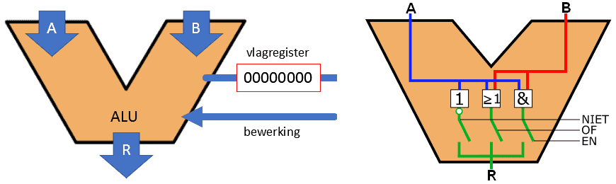
The NOT, OR, and AND gates that we see on the right ALU are the most common gates used for logical operations. There are gates that supplement these three basic gates. We will return to this later on this page. With the NOT, OR, and AND gates, results from inputs can be preprogrammed. Through a circuit that sets an answer as yes/no or true/false to, for example, the handbrake warning light, the light can be activated based on two inputs.
- Is the handbrake engaged?�
- Is the level of the brake fluid reservoir sufficient?
If one or both answers can be “yes,” the warning light is activated. Further examples will follow later on this page.
The table below shows these three basic gates. We mainly use the English terms on this page (AND instead of EN) to avoid confusion for you as a reader, but both are of course correct. The same applies to the symbols (IEC and ANSI). We use IEC symbols, but American literature mainly features ANSI symbols. Again, do not confuse them, and apply one type of symbol.
Below the table, an explanation is given of the characteristics of each gate, and the truth table shows which inputs produce an output of 0 or 1.
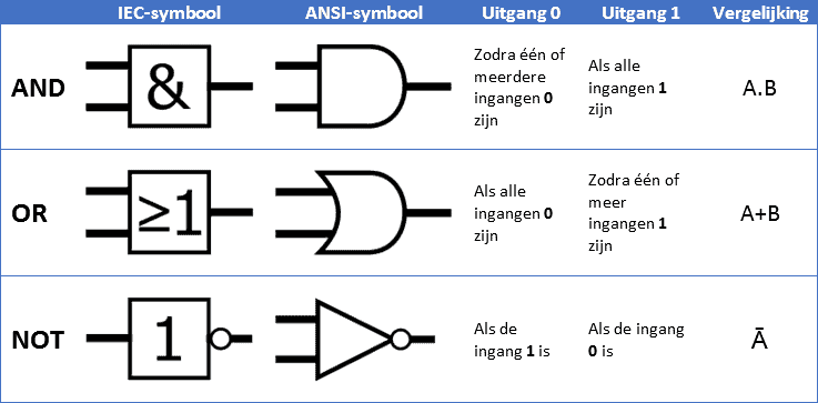
Below is an explanation of the three gates with the symbol and truth table, showing the outputs for different input combinations.
AND Gate:
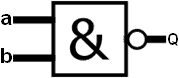
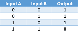
The AND gate can have multiple inputs but always has only one output. In the image, we see inputs a and b. On both inputs, it is possible to set a 1 or a 0 independently. The output (Q) is 1 if both inputs (a and b) are 1. In all other cases, the output Q is 0.
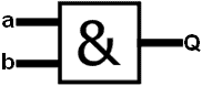
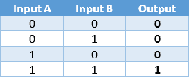
- With two inputs for the AND gate (in this case, input A and B), there are four possible combinations to generate an output. These are shown in the truth table, to the right of the AND gate diagram.
- With four inputs, there are 16 possibilities;
- With eight inputs, there are even 256 possibilities.
OR Gate:
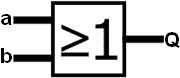
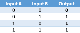
The OR gate can also have multiple inputs, with one output. The output is 1 if one of the two inputs is 1, or if both inputs are 1.
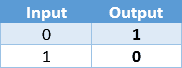
NOT Gate:
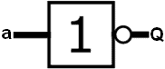
The NOT gate functions as an inverter and has only one input and one output. The input signal is inverted: when the input signal is 1, the output signal is 0, and vice versa.
In addition to the mentioned circuits (AND, OR, and NOT), there are derived logical circuits. These circuits allow us to combine two of the previously discussed circuits into one.
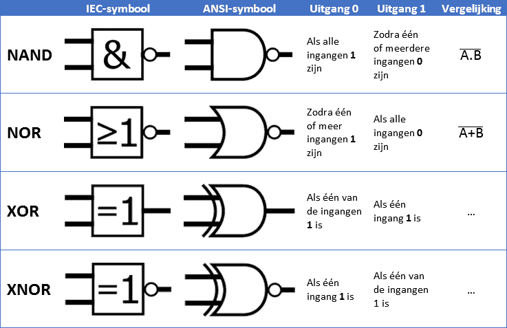
NAND Gate:
The Not-AND gate is an AND gate followed by a NOT gate. The output is 1 if one or more inputs are 1. Only when all inputs are 1 is the output 0. This is exactly the opposite of the previously discussed AND gate.
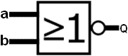
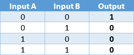
NOR Gate:
The Not-OR gate is an OR gate followed by a NOT gate. It can have multiple inputs and only one output. In this circuit, the output will only be 1 when both inputs are 0.
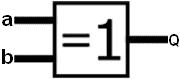
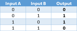
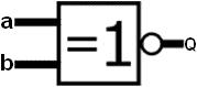
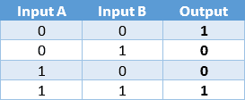
XOR Gate:
The eXclusive-OR gate is a gate whose output is 1 if only one input is 1. When both inputs have the same logical state, the output becomes 0. The XOR gate never has more than two inputs.
XNOR Gate:
The eXclusive-OR gate is equipped with a NOT gate here, making it an eXclusive-NOT-OR gate. The output is inverted compared to the XOR gate.
For each IC, it is important that both power supply and ground are connected to establish a closed circuit. Both gates must also receive voltage to prevent a floating measurement. To ensure proper switching of inputs and outputs, pull-up and pull-down resistors are necessary. Without these resistors, the gates can remain “active” while not being controlled, making them unreliable.
Combinational Circuits and Automotive Applications:
Digital ICs can be linked by connecting the output of one IC to the input of another IC. These combinations can create circuits where any desired input combination can result in a desired output combination. When multiple ICs are linked together, it is called a combinational circuit. To get a feel for combinational circuits, automotive examples follow below.
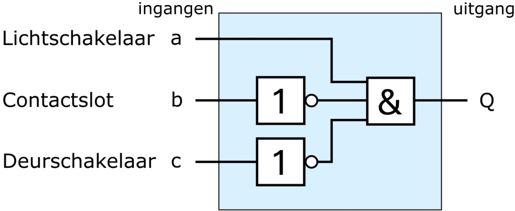
Light Warning Circuit:
A practical example of a combinational circuit is the light warning. When the ignition is turned off and the door is opened while the exterior lights are on, the driver should be warned with a buzzer. The AND gate is used for the three input signals. As described in the previous paragraph, all inputs of the AND gate must be 1 to get a 1 at the output and activate the buzzer. If one of the three inputs to the AND gate is a 0, the output remains 0, and the buzzer stays off.
- Light switch: when the switch is off, a 0 is placed on input a. When the parking or dim light is turned on, this becomes a 1;
- Ignition switch: when the ignition switch is on, a 1 is placed on input b. When the ignition switch is off, it is a 0. The NOT gate inverts this 0 into a 1 to obtain the correct signal for the AND gate.
- Door switch: if a door is open, the signal is switched to ground. As with the ignition switch, the 0 must be inverted to a 1 to make the AND gate function correctly.