Kirchhoff’s Voltage Law:
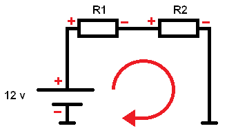
Kirchhoff’s Voltage Law states that the sum of the electrical potential differences is equal to 0. Simply put, in a closed circuit, the incoming and outgoing voltages are equal to 0. The following explanation is about the diagram below with 2 resistors:
In a closed circuit, the total current through the circuit can be calculated using the voltage and resistance values.
-12 + 5 x I + 10 x I = 0
(-12 volts + 5 ohms x the current + 10 ohms x the current = equals 0)
Since this is a series circuit, the resistances can be added together; 5 + 10 = 15a9. Then the current I can be calculated:
I= U / R
I = 12 / 15
I = 0.8A
The total current through the circuit is 0.8A. The current is the same from the battery as at R1 and R2. Now the voltage across the resistors must be calculated. The current and resistance values are known, so the voltage can now be calculated using Ohm’s Law:
UR1 and UR2 are the voltages (U) across the resistors R1 and R2:
UR1 = I x R
UR1 = 0.8 x 5
UR1 = 4v
UR2 = I x R
UR2 = 0.8 x 10
UR2 = 8v
Now Kirchhoff’s Law can be applied;
-Ubattery + UR1 + UR2 = 0
-12v + 4 + 8 = 0
U = 12v
R1 = 5 a9
R2 = 10 a9
I = unknown
This proves that Kirchhoff’s voltage equation holds, because if you start at the bottom left of the diagram at the battery, you start at the negative terminal of the battery. Therefore, you start with -12. If you continue (clockwise) reading the diagram, you first reach the positive terminal of R1 and then R2. Hence, the voltage of the battery (input at the voltage source) is equal to (plus) the sum of all (outgoing) consumers. In this case the resistors. This can be a means of verification in complex diagrams where, for example, equivalent resistors have been calculated. By applying Kirchhoff’s Voltage Law, it can be checked if the calculated data is correct.
Kirchhoff’s Current Law:
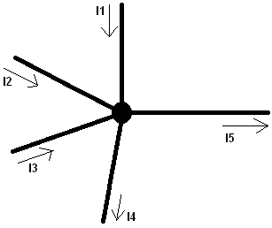
Kirchhoff’s Current Law states that all currents at a node equal 0. All currents entering the node must also exit.
I1 + I2 + I3 + I4 = I5 (all currents exit the node via I5)
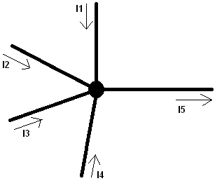
With multiple currents leaving the node, the diagram and formula are as follows:
I1 + I2 + I3 = I4 + I5 (the currents I1, I2, and I3 are distributed over I4 and I5).