Topics:
Introduction:
Electric motors in fully electric or hybrid vehicles operate on alternating current (AC). The energy for the electric motor does not come directly from the battery, as it only supplies direct current (DC). The direct current from the battery is converted into alternating current for the electric motor by the inverter.
In addition, we have converters that increase a low direct current voltage to a higher voltage (boost converter). The battery voltage can be “boosted” for the electric motor (650 volts) or lowered to charge the onboard battery (14 volts). The converter is also used to step down from a high voltage to a low voltage to, for example, supply the interior accessories with a voltage of 12 or 24 volts (passenger cars or heavy commercial vehicles). Click here for the page about the converter.
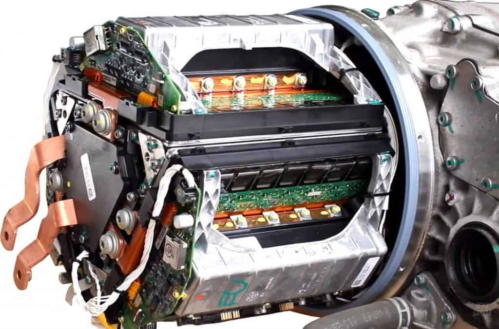
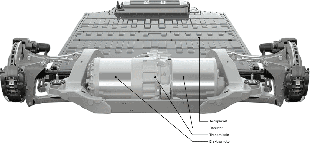
The following images are of a Tesla Model S: the internal parts of the inverter and an overview featuring the so-called “drive unit” where the inverter, transmission, and electric motor are combined in a single unit located near the rear wheel suspension.
Inverter:
The image in the “Boost Converter” paragraph shows an overview with the boost converter, the inverter with twelve IGBTs, and two electric motors (MG1 and MG2).
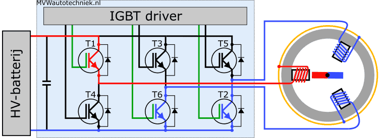
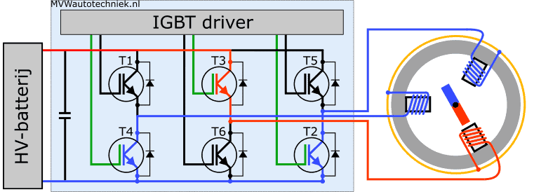
In the bottom seven diagrams, the control of the transistors and the direction of the current to and from the stator coils are shown. The boost converter and the IGBTs + MG2 are omitted for clarity. On the left in the diagram, we see the HV battery pack; this is the high-voltage battery where a voltage of about 200 to 800 volts is stored. Next to the battery on the right, we see a capacitor. When the HV system is activated, the HV safety system initially regulates a limited current from the HV battery pack via a resistor. This is done to slowly charge the capacitor before the HV system becomes fully operational.
We also see a set of high-power transistors. These are the IGBTs that control the electric motor. The IGBTs are controlled by the control unit, indicated as “IGBT driver.” On the right, we see the stator with three coils (U, V, and W) colored in blue and red. In the center of the stator is the rotor that is set in motion by magnetism, see the paragraph on the electric motor.
The upper transistors (T1, T3, and T5) switch the positive connections from the HV battery to the stator coils when the transistors are made conductive by the control unit. The lower transistors (T2, T4, and T6) connect the grounds to the negative terminal of the high-voltage battery.
The gate connections of the IGBTs being controlled at that moment are shown in green. In a synchronous motor, the control unit “reads” the position of the rotor position sensor to determine which IGBT it should control. The rotor position sensor is also known as a resolver.
1. Controlled IGBTs:
- T1: positive (100% controlled);
- T2: ground (50% controlled);
- T6: ground (50% controlled).
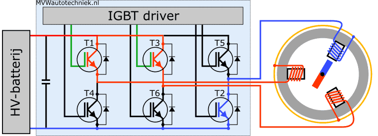
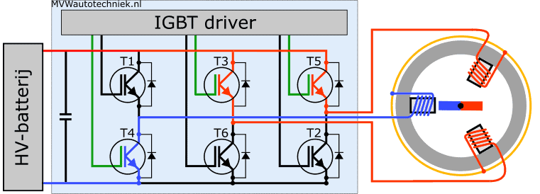
2. Controlled IGBTs:
- T1: positive (50% controlled);
- T3: positive (50% controlled);
- T2: ground (100% controlled).
The rotor turns as a result of the changed magnetic field.
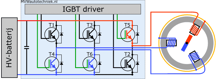
3. Controlled IGBTs:
- T3: positive (100% controlled);
- T2: ground (50% controlled);
- T4: ground (50% controlled).
The rotor turns as a result of the changed magnetic field.
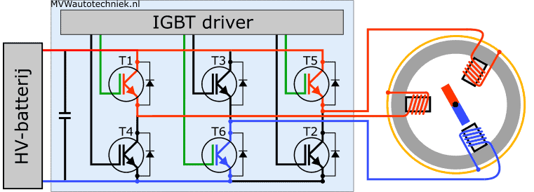
4. Controlled IGBTs:
- T3: positive (50% controlled);
- T5: positive (50% controlled);
- T4: ground (100% controlled).
The rotor turns as a result of the changed magnetic field.
5. Controlled IGBTs:
- T5: positive (100% controlled);
- T4: ground (50% controlled);
- T6: ground (50% controlled).
The rotor turns as a result of the changed magnetic field.
6. Controlled A0IGBTs:
- T1: positive (50% controlled);
- T5: positive (50% controlled);
- T6: ground (100% controlled).
The rotor turns as a result of the changed magnetic field.
7. Controlled A0IGBTs:
- T1: positive (100% controlled);
- T2: ground (50% controlled);
- T6: ground (50% controlled).
The rotor has now rotated 360 degrees (1 full rotation) from the situation in step 1. The cycle with transistor switching repeats again.
The inverter converts the direct current from the HV battery into a single-phase sinusoidal alternating current. The three images below show:
- Left: charging the coil;
- Middle: discharging the coil;
- Right: charge and discharge curve of the coil.
The charging and discharging of the coil are achieved by controlling the base of the transistor with a square-wave voltage. When discharging the coil, the magnetic field collapses, generating a short-duration induction current due to the induction voltage. The flyback diode ensures that the coil discharges.
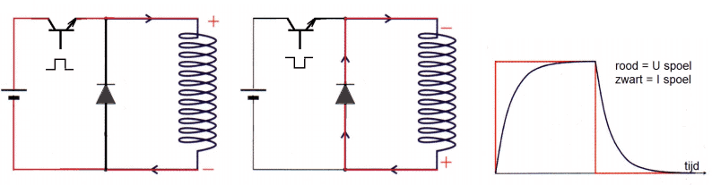
The single-phase sinusoidal shape is obtained by varying the duty cycle with which the transistor is made conductive. The following text pertains to the images below.
- Left: A0 with this frequency, the coil cannot sufficiently charge, resulting in an average voltage;
- Right: the duty cycle is adjusted by the IGBT controller. The charging and discharging times determine the level of current through the coil.
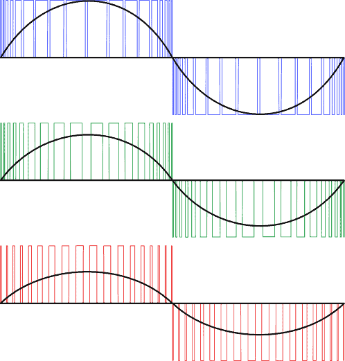
The IGBTs in the inverter are continuously switched on and off. The ratio between the switching on and off is regulated using a PWM system. The wider the pulses (higher duty cycle), the greater the current flowing through the coil, and thus the more powerful the electric motor is. The average current is indicated by the black sine wave. The following image shows three sinusoidal control signals:
- Blue: high control. The duty cycle is high. The current is maximized.
- Green: average control. The duty cycle percentage is lower than with high control. The current is therefore lower.
- Red: low control. Again, the duty cycle percentage has dropped. The current is halved compared to maximum control.
The sine has a half-positive and the other half negative period. The IGBTs in the DC-AC inverter are switched in such a way that an alternating current (AC) is made from a direct current (DC). The current direction through the stator coils is periodically reversed.
by increasing the number of sine waves per unit of time, the rotor speed increases.
The following animation shows the control of the inverter. Below the inverter, you see the time progression of three phases. The rotor rotates in the animation two full rotations (360 degrees). Each rotation is divided into six time units (1 to 6). Below you see colored bars:
- Dark blue: T1
- Green: T2
- Light blue: T3
- Orange: T4
- Pink: T5
- Red: T6
We focus on the first half rotation of the time progression:
- From 0 to 180 degrees, the rotor completes a half rotation. During this period, IGBT T1 is controlled.
- Between 0 and 60 degrees, T1, T5, and T6 were active.
- T1 switches the positive, T5 and T6 ground. Each transistor had its own duty cycle, varying between 50 and 100%.
- At 60 degrees, T2 takes over from T5: the current direction in the coil is reversed.
- At that moment, there is alternating current: because the current direction has changed, the current is negative.
To control the correct coils in the AC synchronous electric motor with the inverter, the inverter looks at the signal from the resolver. The resolver registers the position of the rotor both at a standstill and during rotation.
Regenerative Braking:
During motor braking, the electric motor is used as a generator (dynamo). The vehicle’s kinetic energy is converted into electrical energy: the battery is charged.
The IGBTs are switched off during regenerative braking: the driver does not control them. The rectifier diodes between the source and drain of the IGBTs function as a rectifier to convert the motor’s alternating current into direct current for the battery.
Fully electric and hybrid vehicles have besides the ability to brake electrically, also a conventional, hydraulic braking system to brake with the brake pads and brake discs. The different techniques and control principles can be found on the page: braking of electric vehicles.