Intake Manifold:
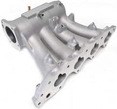
The intake manifold is mounted between the air filter intake pipe and the engine. The manifold pipes are directly attached to the intake section of the engine, right at the intake valves. In indirectly injected gasoline engines, the fuel injector is also mounted in the intake manifold. This injector sprays the gasoline fuel directly onto the intake valve.
An intake manifold isn’t just a series of pipes. Its shape and finish should offer as little resistance as possible to the incoming airflow. All cylinders must receive an equal amount of air. Therefore, the intake pipes for all cylinders should ideally be of equal length. Usually, the intake manifold is made of plastic because it’s cheaper and less susceptible to heating influence from high temperatures compared to, for example, metal. The air in the intake manifold should remain as cool as possible.
Air Pulses in the Intake Manifold:
When an intake valve opens, air is drawn in at high speed. The airflow speed in the intake manifold is high. When the intake valve closes, the air not yet admitted into the cylinder hits the intake valve, causing a pressure increase. This pressure increase generates a wave motion in the intake manifold, moving against the direction of airflow. When the intake valve opens at the moment the pressure wave returns, maximum cylinder filling occurs; the pressure wave ensures extra air enters the combustion chamber. This is rarely the case, as the engine speed varies and thus the intake valve almost never opens at the optimal moment for the pressure wave. In a longer intake manifold, it takes longer for the pressure wave to return to the intake valve than in a shorter intake manifold. For this reason, it’s beneficial to be able to adjust the length of the intake manifold to the engine’s operating conditions (refer to the “variable length intake manifold” section or the application of a so-called Helmholtz resonator).
Helmholtz Resonator:
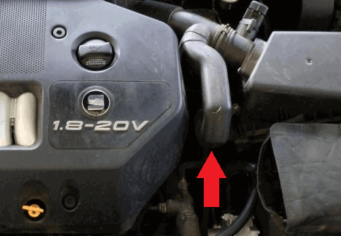
A Helmholtz resonator is a resonance chamber that pressure waves enter, generated by the closing of the intake valve. The resonator is nothing more than an enclosed air chamber connected to the air intake hose between the mass airflow meter and the throttle. An example of a Helmholtz resonator is indicated by a red arrow in the image.
The pressure waves that enter the resonator are reflected back to the intake valve. These pressure waves aid the inward movement of air, ultimately achieving a higher filling rate. The resonator also dampens the intake noise, making the engine quieter. Thus, the engine becomes more powerful and quieter.
Intake Manifold with Swirl Flaps:
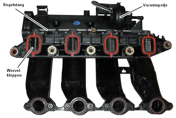
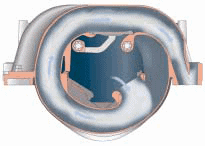
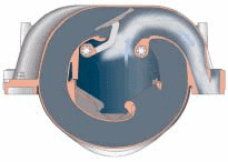
In diesel engines, intake manifolds with swirl flaps are sometimes used. These flaps cause the incoming air to swirl. At low RPMs, the airspeed can be so low (because the turbocharger hasn’t spooled up yet), resulting in insufficient air swirl for proper mixing with the diesel fuel. The injection pressure is unrelated to this. Without the functioning flaps, the mixing with the fuel and thus the eventual combustion wouldn’t be optimal. This leads to increased fuel consumption, less power, and soot emissions.
When the swirl flaps need to be activated, the vacuum chamber is controlled, allowing the control rod to move from left to right. By shifting the control rod, the flaps can be set in the desired position.
Variable Length Intake Manifold:
When designing an engine, the length of the intake channels in the intake manifold must be considered. The length of the intake channels determines the pressure pulses generated by the opening and closing of the intake valve (see the section on air pulses). If these intake channels are always long, the engine will have high torque at low RPMs, but pulling power at high RPMs will continuously decrease. Conversely, if they’re always too short, the engine will only achieve sufficient torque and power at higher RPMs. Applying a variable intake manifold adjusts the length based on driving conditions. Here are two situations:
- Long intake pipe: By giving the air a longer distance to travel and reducing the pipe’s diameter, the air gains higher speed. This is very advantageous at high RPMs with low load or low RPMs with high load (more torque).
- Short intake pipe: The air now travels a shorter distance, providing better cylinder filling at low RPMs with low load and high RPMs with high load (more power).
DISA Valve:
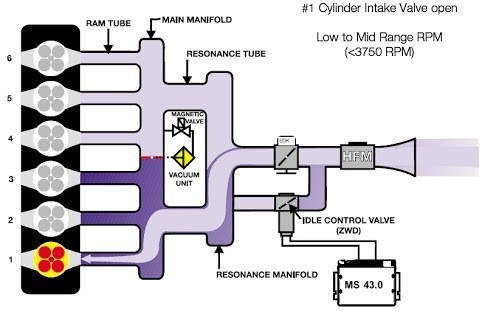
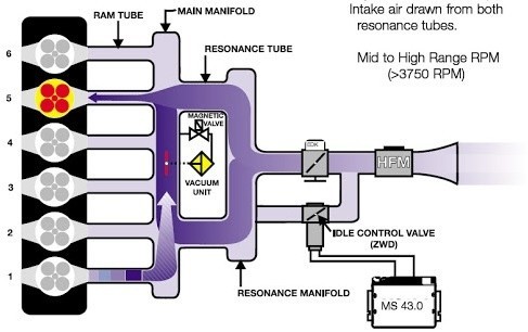
The DISA valve is found in the intake manifolds of BMWs. DISA stands for: DIfferentierte SaugAnlage. The DISA valve ensures that airflow can be blocked in certain parts of the intake manifold at specific RPMs. This divides the intake manifold into two parts. Below is an explanation with three images.
At low or medium RPMs, the DISA valve is closed. From the throttle body, air flows directly to cylinder 1. Guiding the intake air through one section of the manifold to the intake valve results in higher airflow speed. This higher airflow speed causes the air to swirl, allowing for better mixing with the injected fuel.
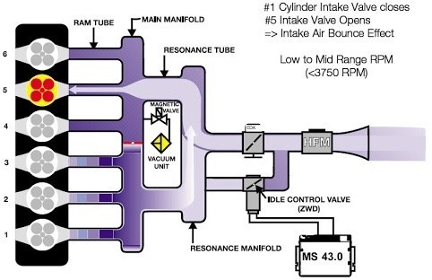
When the intake valves of cylinder 1 close, a pressure wave is generated. With the valve closed, the pressure wave must travel a long way through the resonance tubes to reach the intake valves of cylinder 5. The pressure wave will not influence the airflow of the intake air through cylinder 5.
At higher engine speeds, the DISA valve opens. As the intake length is now extended, higher power is achieved at higher RPMs.
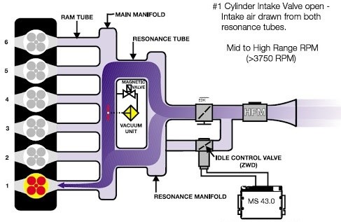
The intake air flows through both resonance chambers. The reflection of the air after the closing of the intake valve of cylinder 1 propels the air to cylinder 5; thus, the filling rate of cylinder 5 is increased.
Exhaust Manifold:
The exhaust manifold isn’t just a series of pipes either. The faster the exhaust gases can flow out, the better. It isn’t just a matter of flow resistance. Attention must also be paid to the opening and closing of the exhaust valves.
Example: A four-cylinder has a firing order of 1-2-4-3. When the exhaust valve of the second cylinder opens, that of the first is still open. As the exhaust period of cylinder 2 begins, the gas escapes under greater pressure than in cylinder 1.
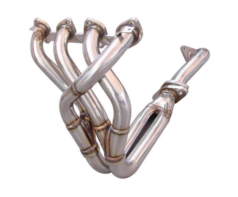
If the manifold doesn’t have the right shape and diameter, the exhaust gases may face interference issues. The exhaust gases from cylinder 1 can oppose those from cylinder 2. In a properly constructed manifold, however, the opposite occurs, and the gases from cylinder 1 help extract the remaining gases from cylinder 2. This is especially the case with a so-called “Spaghetti” manifold (shown in the image below).
In some gasoline and most diesel engines, a exhaust turbo is mounted on the manifold. This is installed as close to the bend in the manifold as possible, to minimize obstruction to the outgoing air.
The loud noise of an engine without exhaust mufflers occurs because the exhaust gases escaping under high pressure and speed cause the air to vibrate. An exhaust muffler helps reduce this pressure and speed.