Introduction:
In vehicles with an internal combustion engine, the heat for cabin heating is taken from the cooling system. The low efficiency of the internal combustion engine (gasoline, diesel, and LPG) is mainly due to heat losses. In the heater core, coolant circulates at a temperature of up to 90 degrees Celsius. The cabin blower forces air through the heater core, so the air enters the cabin warmed. To heat the cabin faster in winter, vehicles with internal combustion engines can also have auxiliary heating systems, in the form of electric heating resistors or a parking heater.
In electric vehicles, the heat source (the internal combustion engine) is missing. As a result, the warm air that the heater must produce has to be generated in another way. This can be done in two ways:
- via electric heating resistors (PTC heater);
- by means of a heat pump (possibly in combination with PTC heating during startup).
Because the heating resistors require a lot of power and can cost up to 10% of the capacity of a fully charged HV battery, the heat pump is becoming increasingly popular. The heat pump is simply much more efficient. The heat pump uses the same components as the A/C system, but by adding extra components the heat pump works as a “reverse” A/C. Knowledge of how the conventional air conditioning system works is therefore required before studying the operation of the heat pump.
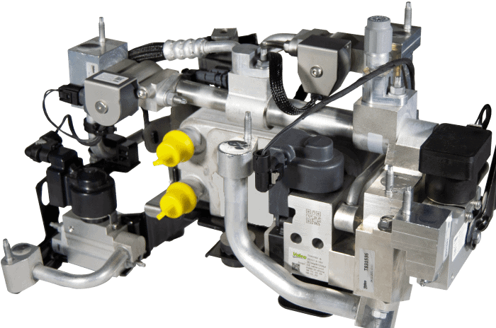
Video showing the layout of the heat pump: Valeo heat pump
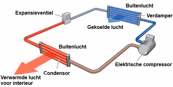
The following image shows the heat pump circuit. A heat pump basically consists of the following main components: a compressor, evaporator, expansion valve, and a condenser.
The compressor moves the gaseous refrigerant under increased pressure to the condenser. As a result of compression, the temperature of the refrigerant rises. The refrigerant releases its heat to the air and condenses. The heated air flows into the cabin. The refrigerant changes from gaseous to liquid.
When the refrigerant flows through the expansion valve, another change of state occurs: here it changes from liquid to gas. In the evaporator, the refrigerant evaporates completely. The required heat of vaporization is extracted from the warmer outside air, which therefore cools down.
The gaseous refrigerant flows from the evaporator back to the compressor.
As the explanation above already shows, the heat pump uses the same components as the A/C system, with the condenser and evaporator swapping roles. The condenser is located under the dashboard and the evaporator at the front of the vehicle near the radiator. The expansion valve has also been given a different location in the system, namely at the front of the vehicle near the evaporator. In addition to heating, the heat pump can also cool: for that, the components are used again as we are used to in air conditioning. By means of switching valves, the condenser and evaporator change function, and the expansion valve will again allow the refrigerant to evaporate in the evaporator under the dashboard.
The heat pump therefore has both a heating and a cooling function. This is not only useful for the cabin, but also for cooling and heating, among other things, the HV battery pack.
Heat pump with R134a or R1234yf:
As briefly described in the introduction, the heat pump can heat and cool both the cabin and the components of the HV system.
In vehicles, we find heat pumps with two different types of refrigerant: the familiar R134a and R1234yf, or R744 (CO₂). The latter is discussed in the next paragraph.
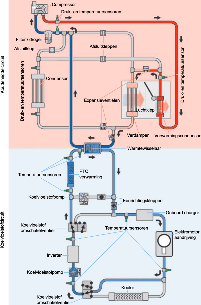
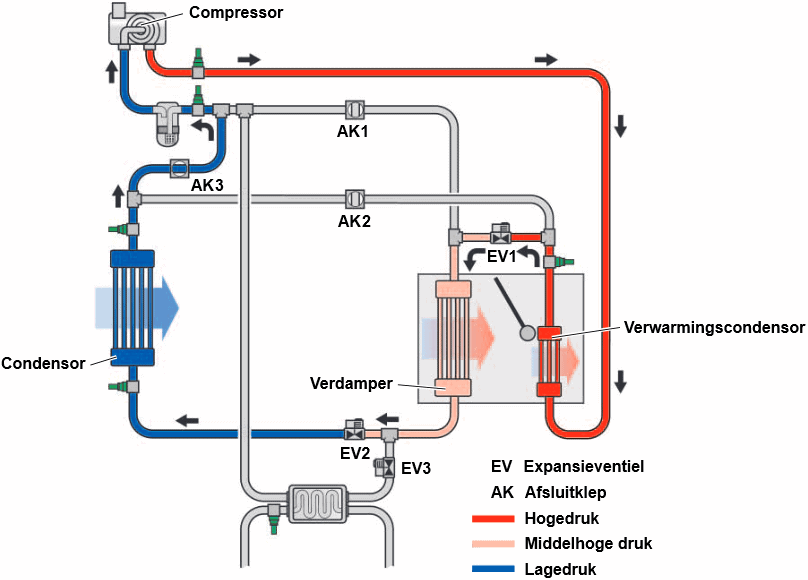
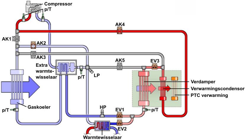
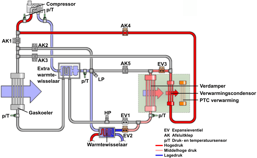
The following image shows two circuits: at the top the red-colored refrigerant circuit and at the bottom the blue-colored coolant circuit. Both circuits are separated from each other, but temperature transfer is possible via a heat exchanger.
The upper circuit focuses on the refrigerant loop. The three shutoff valves route the refrigerant in the correct direction. In addition, there are three expansion valves, which are activated depending on the position of the shutoff valves.
The components are labeled as in an A/C system: the condenser is located at the front near the radiator, and the evaporator in the HVAC housing under the dashboard. In addition, there is a heating condenser, in which the airflow can be directed or blocked by means of an air flap. The heating condenser is used during heating with the heat pump, while the evaporator plays a role during cooling with the air conditioning. Pressure and temperature sensors at multiple locations measure the pressures and temperatures when the refrigerant changes direction via the shutoff valves.
The red lines in the refrigerant circuit indicate high pressure, the blue low pressure. The orange line and the evaporator have a medium-high pressure because an expansion valve is installed on both sides. Arrows indicate the flow direction of the refrigerant.
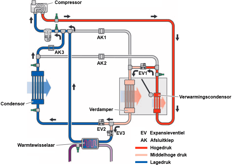
The lower section shows the cooling system of the HV system. The heat exchanger transfers the temperature of the warm coolant to the refrigerant. The cooled HV components include the onboard charger (where AC is converted to DC while charging the battery pack), the traction motor, and the inverter (where the DC from the battery pack is converted into sinusoidal AC for the traction motor).
The coolant switching valves determine the flow direction of the coolant. Arrows show how the flow proceeds in the switched state. The coolant can be routed through the cooler for cooling, or via the PTC heater for heating.
As described above, the heat pump can operate as air conditioning or as a heater. The three situations below show the direction of the refrigerant through the components to make the heat pump function as air conditioning, cabin heating, or cabin heating and HV pack cooling
1. Air conditioning
The (A/C) compressor draws in the gaseous refrigerant through the low-pressure line (blue) and compresses it through the high-pressure line (red) to the heating condenser in the HVAC housing. The air flap is closed, so there is no airflow through the heating condenser and no heat is released. As a result, no condensation occurs.
The refrigerant continues to the condenser via SV2 (shutoff valve 2). In the condenser, the refrigerant condenses and becomes liquid.
After the condenser, the refrigerant reaches EV2 (expansion valve 2). Here it undergoes a pressure drop, causing the refrigerant to evaporate and absorb heat in the evaporator. This heat is taken from the cabin air, which is then blown into the cabin.
From the evaporator, the gaseous refrigerant flows via SV1 (shutoff valve 1) back to the suction side of the compressor.
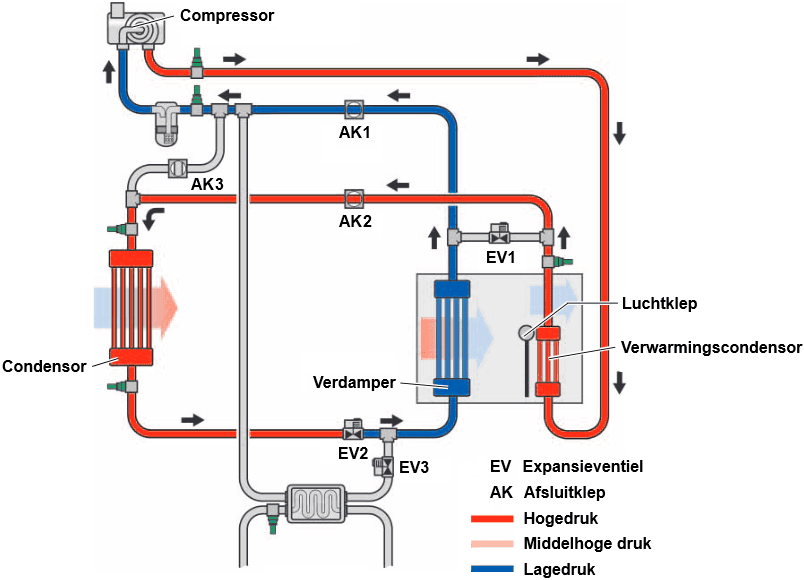
Shutoff valve 3 is closed, so the refrigerant cannot use this line. Expansion valves EV1 and EV3 are also closed, blocking the passage. All expansion valves can operate in two directions. During heating functions, the shutoff valves route the refrigerant in a different direction, while the expansion valves provide pressure reduction in the opposite direction.
2. Cabin heating
The compressor compresses the refrigerant, after which the gaseous refrigerant is transported via the high-pressure line to the heating condenser.
The temperature of the heating condenser rises, so the cabin air, which was preheated earlier in the evaporator, absorbs the heat released when the refrigerant condenses in the heating condenser.
Shutoff valves SV1 and SV2 are closed, so after the heating condenser the refrigerant undergoes a pressure drop in EV1 (expansion valve). This makes the refrigerant partially gaseous. In the evaporator, which in this situation functions as a condenser, the refrigerant condenses again and releases heat to the incoming cabin air. The refrigerant then undergoes another pressure drop in EV2, causing the temperature to drop below ambient temperature. In the condenser, which in this situation works as an evaporator, the refrigerant evaporates and absorbs heat from the outside air, which has a higher temperature. The gaseous refrigerant returns to the compressor via SV3.
In traditional A/C systems, the condenser is located at the front of the vehicle, where the airflow (or airflow from the fan) absorbs heat from the refrigerant and lowers the refrigerant temperature. In a heat pump, however, this heat is not released to the outside airflow, but used to heat the incoming cabin air. In this case, the condenser and evaporator have therefore swapped functions.
3. Cabin heating and cooling HV components
In the heat pump system, the refrigerant must expand for the transition from liquid to gas. There are expansion valves ahead of the condenser (which acts as an evaporator) and ahead of the heat exchanger, which is responsible for heat transfer between the refrigerant and the coolant circuit of the HV components.
EV2 and EV3 are open in this situation. It is also possible that only EV3 is open. In that case, the heat from the cooling system of the HV components is used for expansion. After expansion, the temperature of the refrigerant is lower than ambient temperature. Because of this reduction, the refrigerant extracts heat from the cooling circuit of the electric drive in the heat exchanger. This helps cool the HV components: the coolant carries the heat from, among other things, the inverter and the traction motor, and releases it to the refrigerant via the heat exchanger.
If both the condenser and the heat exchanger generate insufficient heat to allow the refrigerant to condense—for example, if the vehicle is stationary for a long time with the heater on—the PTC heating element is switched on in the cooling system and the coolant temperature in the heat exchanger is increased. The shielded cooling circuit with its own coolant pump prevents sensitive parts such as the power electronics, the onboard charger, and the traction motor from being heated unintentionally. After all, the heating is only intended to allow the refrigerant to expand. This situation will not occur if the inverter and traction motor have to deliver a lot of power: in that case sufficient heat is generated, which may even need to be limited via the cooler.
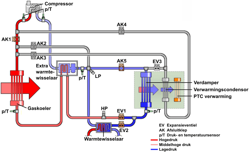
Heat pump with R744 (CO₂):
The refrigerant R744 (CO₂) is being used more and more often in A/C and heat pump systems, such as in electric vehicles. CO₂ has the property of absorbing a lot of heat during evaporation and releasing a lot of heat during condensation. This makes it very effective for heat transfer. An important limitation of CO₂, however, is the critical temperature of 31 °C. Above this temperature, CO₂ cannot condense, which makes it difficult to continue operating efficiently in summer outside temperatures. To address this, vehicles have an additional internal heat exchanger, which uses low-pressure refrigerant between the evaporator and compressor to condense the hot, high-pressure refrigerant in the gas cooler.
Compared with other refrigerants, such as R1234yf, CO₂ has much higher operating pressures. The static pressure at 20 °C is 57 bar, and during operation the pressure on the low-pressure side can rise to 90 bar, with a pressure relief valve that opens at 160 bar. This requires more robust systems, such as a compressor with thicker walls and flexible lines with a corrugated steel sheath for protection against the high pressure and thermal load.
An important advantage of CO₂ as a refrigerant is that it can still heat effectively at extremely low outside temperatures, such as below -10 °C. Unlike R1234yf, which boils at -29 °C, CO₂ remains gaseous at temperatures below -79 °C, allowing it to keep functioning in very cold environments. This makes CO₂ particularly suitable for use in vehicles as both a cooling and heating system, with better low-temperature performance than traditional refrigerants.
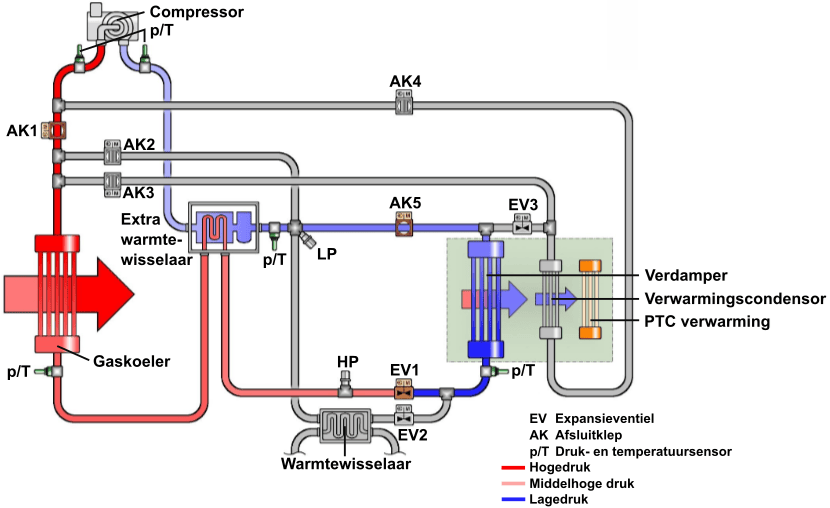
The image above shows the components of the R744 heat pump system (drawing: VAG). Below, seven possibilities are shown of how the heat pump can provide cooling and heating for the entire system, or parts of the system.
1. Cooling the cabin:
The refrigerant flows via the compressor to the gas cooler at the front of the car, where it condenses and releases heat to the outside air. Via the expansion valve (EV1), the refrigerant experiences a pressure reduction, after which it absorbs the warm air from the cabin in the evaporator, causing the temperature of the air flowing into the cabin to drop. The extra heat exchanger between the gas cooler and the expansion valve ensures that the refrigerant cools further so that it fully condenses. At higher outside temperatures, the operation of the gas cooler may be insufficient to fully condense the refrigerant, since the critical temperature of CO₂ is 31 °C.
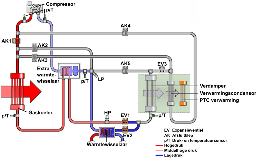
2. Cooling the cabin and HV battery pack:
Just like in situation 1 where only the cabin was cooled, in this situation the compressor moves the refrigerant to the gas cooler at the front of the car. Now EV2 (expansion valve 2 for the heat exchanger) is also open. The two expansion valves (EV1 and EV2) ensure refrigerant expansion to not only cool the air in the cabin, but also the HV battery pack via the heat exchanger (chiller). In this way, the battery pack is actively cooled as soon as the temperature rises above 30 to 35 °C.
3. Cooling the HV battery pack:
The HV battery pack can be cooled without cooling the cabin. When the temperature of the HV battery rises above 30 to 35 °C, the refrigerant is routed from the gas cooler via EV1 and EV2 through the heat exchanger (chiller), where it absorbs heat from the battery and keeps the temperature under control. This cooling is essential for the service life of the battery. To prevent refrigerant from flowing through the evaporator, shutoff valves SV3, SV4, and SV5 are closed.
4. Reheat phase:
In the reheat phase, the cooled air coming out of the evaporator is heated again using the heating condenser.
The reheat function is used at low outside temperatures, for example when the windshield needs to be defogged while the humidity is high. The dry, cold air from the evaporator is warmed up, so the cabin is heated and dehumidified at the same time.
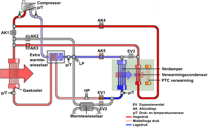
5. Air heat pump:
Just like with the R134a heat pump, the gaseous refrigerant flows from the compressor through the heating condenser and the evaporator, where heat from the refrigerant is released to the incoming cabin air.
However, when starting up the CO₂ heat pump, it takes some time before the heating condenser reaches a sufficient temperature to bring the cabin air to the desired temperature, because heat cannot yet be extracted from the HV circuit.
To get heat in the cabin immediately after starting the car, the PTC heater is activated.
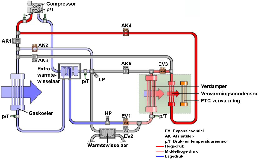
6. Air-to-water heat pump:
Just like in situation 6, the heat pump can absorb heat from the outside air, but in this situation heat is also extracted from the cooling system of the HV battery pack.
Via the compressor and the open shutoff valve AK4, the refrigerant is routed to the heating condenser and the evaporator, where it releases heat to the incoming cabin air. At the same time, the refrigerant flows via EV1 through the gas cooler at the front of the car, where it absorbs heat from the outside air, and via EV2, where it absorbs heat from the cooling system of the HV system.
7. Water heat pump:
At low outside temperatures, the CO₂ heat pump can also function as a water heat pump, where the refrigerant extracts heat from the HV cooling system and releases it to the cabin or other vehicle systems.
Via the compressor, the refrigerant is routed under high pressure to the heating condenser and the evaporator to heat the incoming air. The refrigerant then expands via expansion valve 2 in the heat exchanger (chiller), and is then drawn into the compressor via the additional heat exchanger.
Related pages: