Introduction:
The fuel pump is a component of the fuel system. The components used are described on the page fuel system gasoline engine.
In a vehicle with a gasoline engine, three types of fuel pumps can be used: the mechanically driven pump, electric lift pump, and the high-pressure fuel pump. This page describes the operation and application of each pump.
Mechanically Driven Fuel Pump:
In gasoline engines equipped with a carburetor, a mechanically driven fuel pump was often used. The image shows the mechanically driven fuel pump of a classic Land Rover engine from the 1970s, which was retrofitted with a computer-controlled engine management system in 2017-2018. The fuel pump is circled in red.
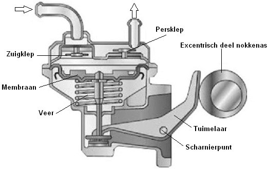
The pump is driven by an eccentric operated by the camshaft. The operation of the rocker arm causes the diaphragm in the center to be pulled downward. The vacuum in this space opens the suction valve, allowing fuel to flow into the fuel chamber. As the eccentric part of the camshaft rotates further, the spring pushes the diaphragm back into place. The pressure in the fuel chamber opens the delivery valve, forcing the fuel out of the pump under increased pressure. The fuel then reaches the carburetor via a line.
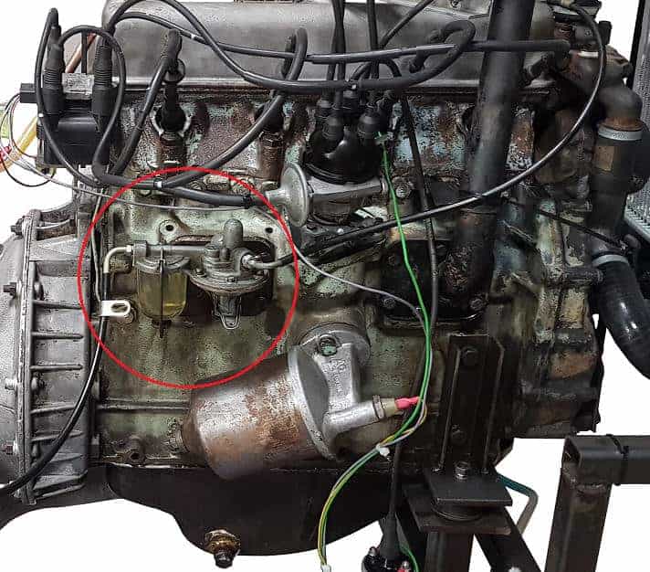
If the vehicle has been standing for a long time and/or the float chamber in the carburetor is insufficiently filled with gasoline, a lever on the mechanical fuel pump can be used to pump gasoline. The lever, like the rocker arm in the image, is connected to the diaphragm, which is not visible in the image.
Mechanical fuel pumps often have a sight glass that also serves as a settling chamber. This sight glass must be cleaned regularly. The system with carburetor and mechanical fuel pump, especially those with long suction lines, are prone to vaporlock (vapor lock).
Electric Lift Pump:
Vehicles with electronic fuel injection use an electric lift pump. The fuel pressure is significantly higher: 3 bar with the electric pump compared to 0.3 bar with the mechanical fuel pump, making it ten times higher. The pump also activates immediately when the ignition is switched on, bringing the fuel system to the correct pressure before the engine starts.
Today, electric fuel transfer pumps are located inside the fuel tank. Sometimes they are placed outside the tank, specifically between the tank and the fuel rail. The advantage of mounting them in the tank is that the pump is cooled by the surrounding fuel.
Below is a diagram of a two-stage pump. This type is present in every modern vehicle. These pumps contain two independently operating pump units: the impeller pump (left image) and the gear pump (right image). Both pumps are driven by separate electric motors. The first stage transfers fuel from the tank via the filter to the buffer reservoir, which has a capacity of approximately 600 milliliters. This internal reservoir ensures that when a vehicle makes prolonged turns with a low fuel level, the gear pump (2nd stage) still receives fuel. Without a filled reservoir, all fuel would shift to one side of the tank, causing the pump to be unable to draw any fuel. This system prevents that.
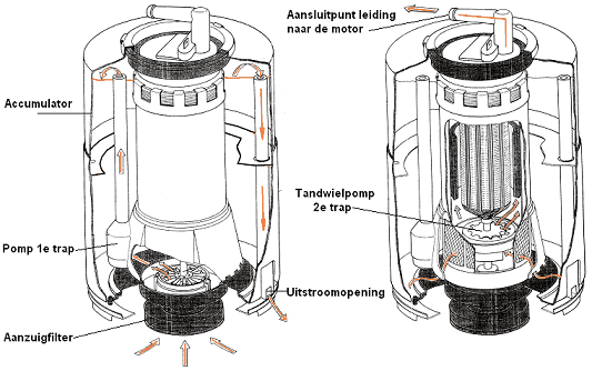
The fuel in the buffer reservoir is transported by the gear pump under a pressure of up to 3 bar (via the line at the upper connection point) to the engine. This allows for a pump output of 80 liters per hour, far more than necessary. The explanation for this is provided in the text under the image.
The pump delivers significantly more fuel than the engine actually needs. This is intentional to keep the system constantly under pressure. If the system were pressure-free, the fuel in the lines could heat up due to external influences, potentially causing vapor bubbles (vapor lock). Keeping the system constantly pressurized prevents this. Therefore, not all fuel being pumped forward is utilized. A return line is installed, managed by the pressure regulator. This fuel return line routes fuel back from the engine compartment to the fuel pump in the tank. The return fuel then re-enters the tank.
The pump maintains a constant rotational speed. Whether the engine is idling or producing power, the lift pump always delivers fuel under the same pressure to the engine. When the engine is idling, more fuel returns to the tank than when the vehicle accelerates.
Fault Symptoms of the Fuel Pump:
The electric fuel pump ensures that fuel is pumped from the tank to the engine. If the pump fails, the engine will not receive fuel. It’s not always immediately clear that the fuel pump is malfunctioning. In some cases, the pump still operates but does not reach the desired pressure. Low delivery pressure can cause the following symptoms:
- The maximum engine power decreases.
- There is cylinder misfire.
- The engine struggles to start.
- Error codes are stored in the ECU.
In many instances, a low-pressure fuel sensor is installed on the supply line. This sensor sends the fuel pressure value to the ECU. If the fuel pressure is too low, the ECU will store a fault code. If no pressure sensor is present, the technician must connect a manometer to the fuel rail to verify current fuel pressure. The technician can determine whether the correct pressure is achieved or if it remains too low based on the readings.
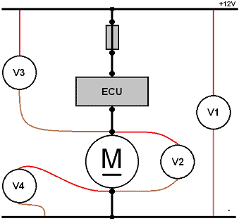
A low fuel pressure does not necessarily mean the fuel pump is defective. Low supply voltage, poor ground connection, or a bad connector can also cause the pump to receive insufficient power to function properly. In case of low fuel pressure, it’s advisable to measure the connector voltage while the pump operates. Never disconnect the connector to measure it, as this breaks the circuit and will not reveal a voltage drop due to a transition resistance!
Example:
There is a transition resistance in the positive wire. A V4 measurement (see diagram) can help identify this. The V3 (voltage drop in the positive) might show 4 volts, indicating the pump effectively operates with 8 volts instead of 12 volts (measurement V2). When the pump connector is removed, the circuit is interrupted, eliminating the voltage drop from transition resistance. In this case, 12 volts are measured at the connector. A voltage drop only occurs with a closed circuit and active consumer, so the connector should not be removed while measuring. Alternatively, measure under load with a connected lamp.
High-Pressure Fuel Pump:
The high-pressure fuel pump of a gasoline engine with direct injection is almost always driven by the camshaft of the engine. The pump is mounted on top of the valve cover for easy access. During repairs, the pump can be easily removed (after depressurizing the fuel rail). Unlike diesel engines, this pump doesn’t operate on “timing.”
The image depicts a V8 engine with 8 injectors. The fuel pump is mounted on the valve cover (the valve cover itself is not visible in the image). Fuel from the lift pump in the tank is supplied to both high-pressure pumps via the fuel supply line (4) at a pressure of 5 bar. When the camshaft pushes the plunger in the fuel pump, a pump stroke is created. This process compresses the fuel at high pressure into the line (9). The fuel then reaches the fuel rail (also called the fuel gallery), where it is evenly distributed under pressure to the high-pressure lines (7) of each injector.
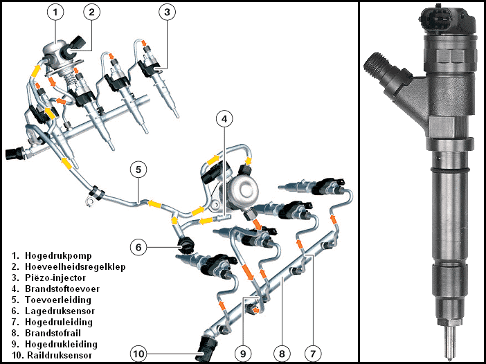
Each injector has a plug connection. This connects each injector to the engine control unit (ECU). The ECU determines, based on core maps (calculated from input signals such as temperature sensors and speed sensors), when and how long each injector sprays fuel. The injection pressure usually ranges around 200 bar with a maximum of about 250 bar (depending on brand/type).
Each fuel rail is fitted with a rail pressure sensor that continuously monitors the pressure in the rail. This data is sent to the ECU, which uses the information to manage the high-pressure fuel pump. The ECU decides whether the pump’s fuel pressure should increase, decrease, or remain constant.
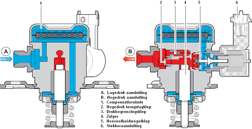
Through low-pressure connection A, fuel from the lift pump in the tank enters the compensating chamber 1. Via the quantity control valve 5, fuel enters the fuel chamber.
Piston 4 is driven by the camshaft. In its neutral position, the piston is at its lowest point, pressed down by a spring. When the camshaft pushes the piston against the spring force upwards, fuel is compressed through the high-pressure check valve into the line (via connection B). The pressure relief valve (3) opens if the injection pressure is too high. If this valve partially opens during piston compression, some fuel returns to the fuel chamber, lowering the pressure, as with a fully open valve, the fuel pressure before and after the piston is equal. From connection B, the fuel reaches the injectors via the fuel rail, injecting fuel at the end of the compression stroke.
Click here to go to the page for the high-pressure fuel pump of the diesel engine.