High-pressure inline pump (PE):
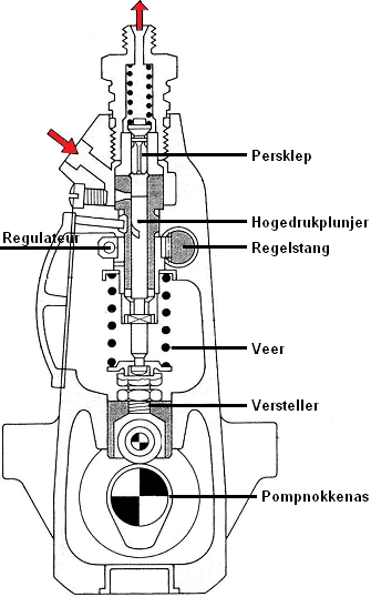
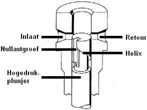
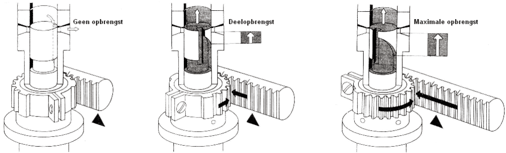
The high-pressure inline pump represents the first generation of diesel fuel pumps. A high-pressure inline pump consists of as many plunger elements as there are cylinders. Each plunger supplies the fuel for its own cylinder. The high-pressure plungers are operated by the internal pump camshaft. When these plungers are pushed up, they cause the pressure stroke (forcing diesel through the line to the cylinder). The high-pressure inline pump operates with a fixed stroke. The fuel output is regulated by rotating the plungers. This rotation is executed by the control rod, which is indirectly connected to the accelerator pedal. When the accelerator pedal is pressed, the plungers rotate, thereby regulating the fuel output.
The pump also contains the governor (visible in the images below), which maintains a stable idle speed of the diesel engine and adjusts the fuel output as the speed increases.
An inline pump suffers from internal leakage losses. These are mainly due to imperfections in the cylinder seal: the cylinder wall can be microscopically uneven, allowing room for leakage along the piston. At lower speeds and pressures, small amounts of diesel fuel may leak past the plunger seals or other internal components. This leakage can occur when seals don’t close perfectly or due to wear over time.
As the pump speed increases, the pressure inside the pump typically increases. This higher pressure can help reduce imperfections in seals and components, thus reducing leakage losses. This is because the higher pressure forces the seals against the moving parts, reducing the chance of leakage.
When the fuel supply is not properly regulated, excessively injecting fuel into the engine can lead to a high cut-off speed. a0
- If there is a malfunction in the fuel control of the inline pump, the plungers may inject more fuel than needed for the current speed. This can lead to excessive combustion speed and a higher than recommended engine speed.
- If the control rod responsible for adjusting the fuel output becomes defective, the inline pump may not respond correctly to the accelerator pedal. This can result in an unintended increase in fuel supply and thus engine speed;
- Physical malfunctions in the inline pump, such as stuck plungers, damaged parts, or mechanical blockages, can disrupt the normal fuel supply regulation and potentially lead to an uncontrolled higher speed.
Rotary distributor pump (VE):
As a successor to the high-pressure inline pump, the rotary distributor pump (the CAV DPA and Bosch VE) was developed. This fuel pump is entirely mechanical. The advantage of the rotary distributor pump compared to the inline pump is the reduced number of plungers (and consequently the installation size) and the standard injection adjustment.
Bosch VE-pump:
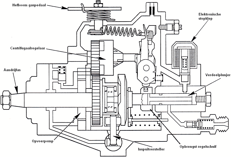
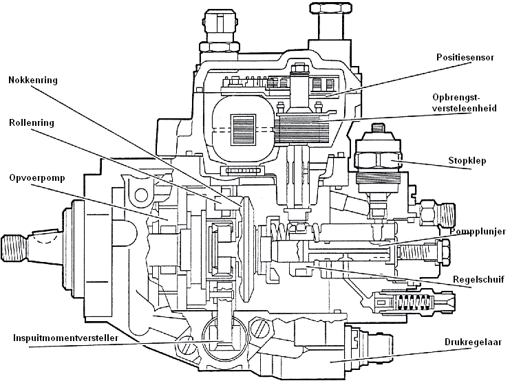
The Bosch rotary distributor pump is a fully mechanical pump. The lever on the pump is directly connected to the accelerator pedal. The pump operates with a plunger that moves axially. The plunger makes both a rotary and a reciprocal movement (explained in more detail below). The control slider (connected to the accelerator pedal) and the centrifugal governor ensure the correct fuel dosing. When the control slider moves to the left, fuel can exit the pump via the return opening, reducing the fuel amount. When more fuel is needed (higher speed or load), the control slider moves further to the right, increasing the fuel volume to the injectors. With a constant engine load, the speed increases accordingly.
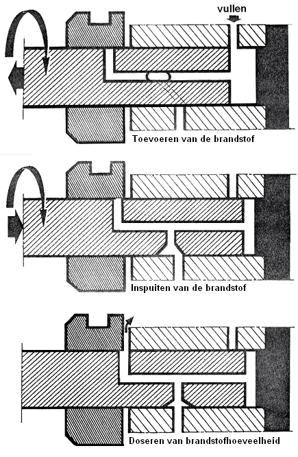
The plunger in the Bosch VE rotary pump facilitates the feeding, injecting, and distributing of the fuel. These three steps are explained below with the help of three illustrations.
1. Fuel supply:
The plunger is turned to the left, allowing fuel – from the lift pump – to flow via the inlet channel above the plunger to the pressure chamber to the right of the plunger. 0a0
2. Fuel injection:
The cam disk pushes the plunger to the right. Thus, the inlet channel to the pressure chamber is closed, and the volume in the pressure chamber shrinks. The pressure on the fuel increases until a connection with the outlet channel is made through the rotation. Every 90 degrees, there is an exit where the fuel is forced under pressure.
3. Fuel quantity dosing:
The position of the control slider determines the end of the injection and thus the amount of fuel delivered via the outlet to the injector.
The control slider position is determined by the centrifugal governor. This component is described below.
Centrifugal regulator:
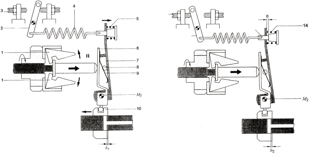
The accelerator pedal is indirectly connected via spring 4 and the lever system (6, 7, 8, 9) to control slider 10. In the depicted position (left), the accelerator pedal is fully pressed, causing the control slider to move to the right for maximum output. M2 is the pivot point. When the regulated speed is reached, the centrifugal force attempts to move the regulating sleeve II to the right, causing control slider 10 to move to the left. Thus, an equilibrium is created between spring 4 and the centrifugal force. The speed is regulated by adjusting the output. 0a0
The right illustration shows the regulation at idle speed. The accelerator pedal is not pressed, and the lever is entirely in the right position. A weak spring (14) now ensures the equilibrium.
Injection advancement:
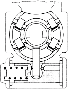
Rotary fuel pumps are always equipped with injection advancement as standard. As the speed increases, earlier injection is needed for a proper power stroke. Otherwise, the diesel mist injected by the injector won’t have enough time to mix well with the air at higher speeds. Hence, the injector must advance a few degrees before the TDC (Top Dead Center) as the speed increases. The injection advancement system consists of a plunger connected with a roller ring. As the speed increases, this roller ring rotates along with the rotational direction, causing the injection plunger to begin the pump stroke (and hence the injection) earlier. This injection advancement does not utilize electronics.
Adjusting the rotary distributor pump:
It is vital for the pressure build-up in the pump to occur at the right moment. The pressure build-up determines the injection timing of the diesel through the injectors. The position of the fuel pump can be altered relative to the engine block. There are slots in the engine block allowing the fuel pump to be shifted. Adjusting the pump doesn’t affect the gear driven by the timing belt. The gear stays in place, but the pump behind it is repositioned. In a distribution that rotates clockwise, the following applies:
- Moving the pump counterclockwise results in earlier injection;
- Moving the pump clockwise results in later injection;
The fuel pump should thus be adjusted based on the crankshaft position and the position of the control slider. This must be done using a dial gauge.
Below is a step-by-step guide to adjusting a rotary distributor pump.
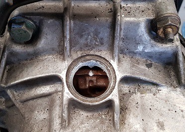
1. Position the piston of cylinder 1 at TDC.
Rotate the crankshaft until the piston of cylinder 1 is at top dead center.
You can check if the crankshaft timing is set correctly by seeing if the mark on the flywheel corresponds with the mark in the transmission housing.
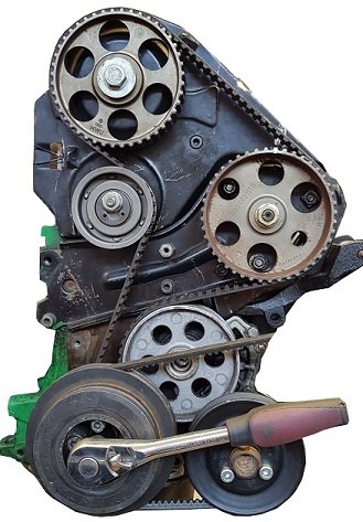
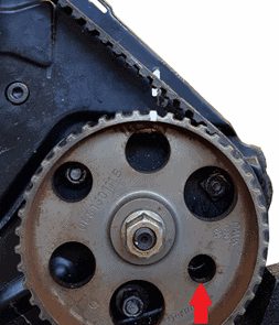
2. Fuel pump timing
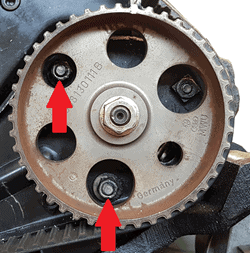
Check whether the timing of the fuel pump is correct. The two marks (highlighted in white in the image) should align. If the fuel pump is not timed correctly, the timing belt needs to be dismantled and installed correctly.
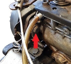
Then insert the locking pin (in the image in the hole indicated by the red arrow).
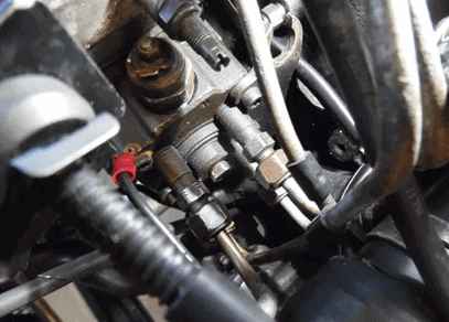
3. Dismantling parts
Dismantle the fuel lines, coolant hose, and thermostat housing to create space behind the fuel pump. This space is needed to mount the dial gauge in the pump.
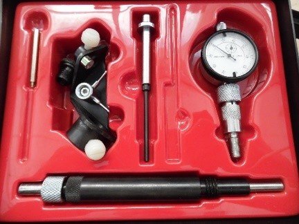
4. Dial gauge
Find the dial gauge used to adjust the fuel pump.
Screw the loose parts of the dial gauge together. Remove the blind plug in the fuel pump and screw the dial gauge in. Make it easy for yourself by positioning the dial gauge so it’s clearly visible when the crankshaft is turned.
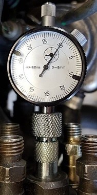
4. Set a preload.
Because you want the dial gauge needle to always be in contact with the inside of the pump, set a preload. This will push the dial gauge further into the pump housing.
Set this preload to at least 2 millimeters (see image).
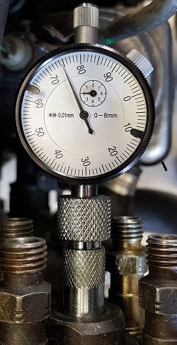
5. Rotate the crankshaft in the normal direction.
The crankshaft must be rotated. The dial gauge needle will move as a result. As the distributor plunger makes a reciprocating motion, the needle will eventually stop. As the crankshaft continues to rotate, the needle will move back.
At the point where the needle stops, the maximum stroke of the distributor plunger is reached.
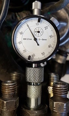
6. Zero the dial gauge.
Rotate the black ring on the dial gauge and set it to 0.
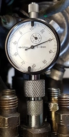
7. Place the piston of cylinder 1 at TDC.
Rotate the crankshaft again until the piston of cylinder 1 is at TDC. Again, check the marks on the flywheel and transmission housing.
Read the value indicated by the dial gauge needle. The needle has moved counterclockwise. This means the distributor plunger has traveled
0.70 mm. Compare this value with factory values. If they match, no adjustment is needed. If the value is incorrect, the pump should be adjusted.
8. Adjust the fuel pump.
Adjust the fuel pump by loosening the three bolts (indicated in the images) a turn and shift the pump’s position on the engine block.
Electronically controlled distributor pumps:
Nowadays, diesel engines, like gasoline engines, are managed with an ECU (Engine Control Unit, a control computer). Through this computer, various functions of the high-pressure fuel pump 0a0are controlled, allowing the fuel dosage to be more accurately regulated than with a fully mechanical fuel pump. Electronically controlled distributor pumps are categorized into the following three types:
- Lucas EPIC pump
- Bosch VP-/ VR-pump
- Bosch VP44
Lucas EPIC pump:
The Lucas EPIC pump is a fully electronically controlled rotary fuel pump. The following functions are regulated: start output, idle speed regulation, part-load output regulation, full-load regulation, injection timing regulation, and self-diagnosis.
Bosch VP pump:
The Bosch VP pump is internally identical to the mechanical VE pump described earlier on this page. Components such as the lift pump, cam ring, control slider, pump distributor housing, and pump plunger remain unchanged.
The VP pump has the following new components compared to the VR pump:
- Actuator for regulating the position of the control slider.
- Sensor to determine the control slider’s position.
- Injection timing adjuster; controlled via PWM signal. (PWM stands for Pulse-Width Modulation). The PWM signal comes from the ECU.
The actuator adjusts the control slider’s position. This is done using a permanent magnet and an electromagnet controlled by a duty-cycle. When the ECU powers the electromagnet, it becomes magnetic and is attracted to the permanent magnet. The longer the duty-cycle signal, the more magnetism is generated and thus the greater the movement (adjustment). When the duty-cycle signal is lost, the spring pulls the adjuster back.
The position sensor is an inductive sensor that checks the rotation of the axis of the aforementioned control slider. This provides the ECU with feedback that the desired positions are also achieved.
Injection advancement:
The injection advancement system is similar to that of the Bosch VE pump. However, in this VP pump, the advancement is controlled by a PWM signal from the ECU. In short, the ECU determines the position of the roller ring and not the engine speed, as was the case with the VE pump.