Fuel Supply and Return System:
The fuel supply system ensures that the fuel is transferred from the tank to the engine. The electric fuel pump draws fuel from the tank and transfers it via the supply line and through the fuel filter to the fuel gallery (also known as the fuel rail).
At the injector entrances, the fuel pressure is present. When an injector is activated by the ECU, fuel is injected into the cylinder. The pressure regulator prevents excessive rail pressure. When the rail pressure rises too high, the pressure regulator ensures that the fuel flows back to the fuel tank via the return line.
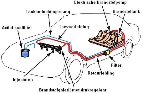
As the fuel level drops, more air must enter the fuel tank; otherwise, there is a vacuum. Conversely, at a rising tank level, such as when refueling, air must escape from the tank. The vapors released must not enter the atmosphere. That’s why an activated carbon filter is used to manage the ventilation and purging of the fuel tank. Through a tank ventilation hose, the tank is supplied with or depleted of air via the tank ventilation valve.
The following sections describe the components of the gasoline engine’s fuel system.
Fuel Tank:
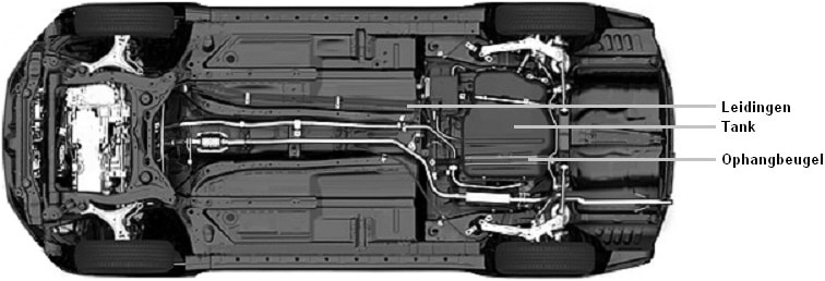
The function of the fuel tank is to store fuel. The fuel tank is almost always mounted at the rear of the car, near the rear wheels, under the rear seat. The tank is attached to the body with mounting brackets. The fuel tank is never located within the vehicle’s crumple zone. The fuel tank is almost always made of plastic due to its lightweight and the ability to create various shapes. By shaping the tank so that every available space is utilized, the largest possible capacity is created.
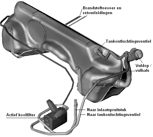
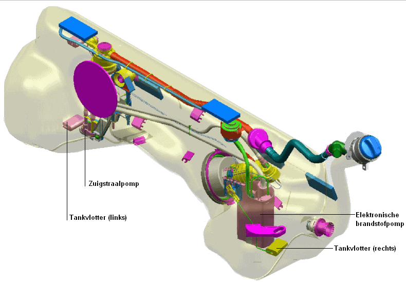
The fuel tank in the image below is called a ‘saddle tank’ due to its shape. It is installed on a rear-wheel-drive car. The central hump provides space for the drive shaft. In a front-wheel-drive car, the tank would be flatter on the bottom. The fuel pump in the tank ensures the fuel supply to the engine. A so-called jet pump is also employed in a saddle tank to transfer fuel to the other tank half. The operation of these fuel pumps is described later on this page.
There are always 2 fuel lines running from the tank to the engine, namely a supply line and a return line. As the name suggests, the supply line transports the fuel from the fuel pump to the engine. The return line returns the excess fuel back to the tank. The tank always has a tank ventilation valve connected to the activated carbon filter via a ventilation hose.
Activated Carbon Filter:
In the image above, the activated carbon filter is depicted. The activated carbon filter ensures that HC emissions (fuel vapors) do not enter the atmosphere. This filter extracts fuel vapors from the tank and filters them through the special activated carbon material. After the fuel vapors are filtered, they are discharged to the atmosphere or the engine’s intake system. The vapors are mixed with the intake air and then burned, ensuring that the fuel vapors are evacuated as cleanly as possible.
The activated carbon filter can be mounted near the fuel tank, but sometimes it is located under the hood. In some cars where it is mounted under the hood, a ticking sound can sometimes be heard that often comes and goes. That is when the activated carbon filter is working.
Fuel Pump:
In classic cars, we often find a mechanical fuel pump driven by the camshaft. The mechanical fuel pump has been replaced by an electronic booster pump, which provides the necessary pressure for an indirectly injected gasoline engine. Nowadays, (almost) all car manufacturers use direct high-pressure injection; fuel is injected directly into the combustion chamber at a high pressure. This high pressure is achieved with the high-pressure fuel pump.
The operation and application of these fuel pumps are explained on the page Fuel Pump of the Gasoline Engine.
Jet Pump:
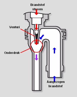
As described in the second paragraph, the saddle tank consists of two parts. The fuel levels on both sides must be kept equal. The jet pump transfers fuel from one side of the tank to the other. The fuel ends up in the tank half where the electric fuel pump is located. The electric fuel pump transfers the fuel to the engine.
A vacuum is created in the jet pump. By allowing fuel to flow through a restriction, the fluid flow is accelerated (see the image below). This creates a vacuum after the restriction, allowing fuel to be drawn in. A jet pump operates on the same venturi principle as a carburetor, except the venturi effect is achieved by fluid flow instead of airflow.
Float:
A float in the fuel tank has the task of measuring the fuel level and transmitting this signal to the instrument panel. The tank content can be read there. If equipped with an onboard computer, the estimated driving range will be calculated based on driving style. The float has a foam part. This foam block floats on the fuel. When the fuel level drops, the foam block also drops. This mechanical movement causes a needle to move over a potentiometer (a variable resistor). A high or low resistance results in a low or high current. Based on this current strength, the needle on the instrument panel moves from low to high.