ESP Introduction:
ESP stands for Electronic Stability Program and works in conjunction with ABS and ASR. When a vehicle is equipped with ABS (Anti-lock Braking System) and ASR/ASC (Anti-Slip Regulation / Control), the ESP system can be added using a number of additional sensors and software adjustments. Components such as the wheel speed sensors and the ABS pump/control unit are also used by the ESP system. The ESP system also reduces engine power by closing the throttle more or by retarding the ignition.
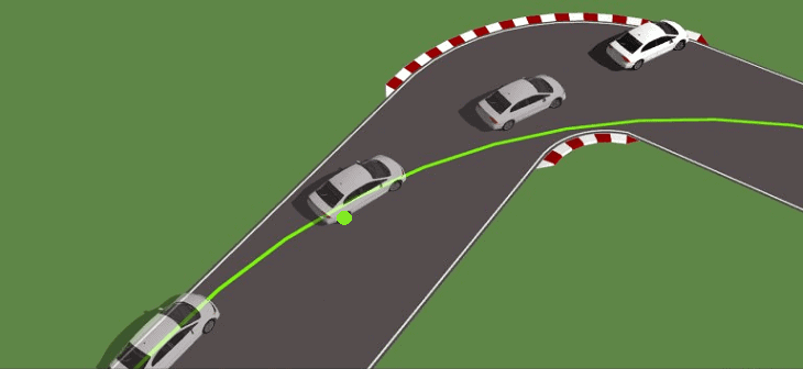
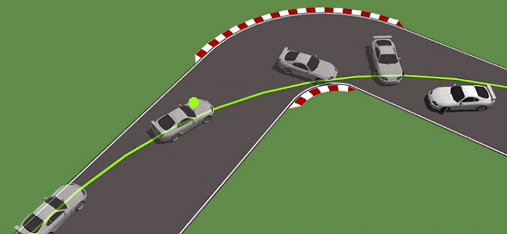
The goal of the ESP system is to improve cornering behavior (understeer and oversteer). This applies to situations such as braking during a turn or when taking an evasive maneuver. The ESP system brakes one wheel of the vehicle so that normal steering behavior is regained. Below are depicted two situations where the green indicated wheel is braked. By braking, the vehicle will follow the green line instead of becoming uncontrollable. At the bottom of this page, the various necessary ESP components are described.
Auto manufacturers often use their own names for ESP in their models, even though the function is the same. These different names are given to make the system seem “luxurious” compared to standard ESP. Examples include:
- ASC + T: Automatic Stability & Traction Control (old generation BMW pre-1996)
- DSC: Dynamic Stability Program: BMW, Jaguar, Land Rover, Mazda, Mini
- DSTC: Dynamic Stability and Traction Control (Volvo)
- ESP: Electronic Stability Program (Alfa Romeo, Audi, Cadillac, Chevrolet, Chrysler, Citroen, Fiat, Ford, Hyundai, Jeep, Kia, Mercedes, Mitsubishi, Nissan, Opel, Peugeot, Renault, Saab, Seat, Skoda, Smart, Suzuki, Volkswagen)
- PSM: Porsche Stability Management (Porsche)
- VDC: Vehicle Dynamic Control (Alfa Romeo)
- VDCS: Vehicle Dynamic Control System (Subaru)
- VSC: Vehicle Stability Control (Lexus, Toyota)
- VSA: Vehicle Stability Assist (Honda)
Understeer:
Understeer occurs when the front tires no longer grip the road surface sufficiently. The car will make a wider turn than intended, tending to go straight. The front wheels will slide towards the outside of the turn. Understeer can be corrected by ensuring the front wheels regain adequate grip on the road. This can be achieved by reducing throttle or steering input. Steering more does not help with understeer and can make it worse as the wheels lose even more grip. Most car manufacturers tune the chassis so that the car tends to understeer rather than oversteer. The reason is that the average driver will immediately release the throttle in such a situation, which can help the car regain grip.
Oversteer:
Oversteer occurs when the rear tires lose grip on the road surface. The rear tires of the car will slide towards the outside of the turn. The rear end wants to overtake the front end, causing the vehicle to potentially spin around its axis. Oversteer can be corrected by counter steering and reducing throttle in rear-wheel-drive cars (e.g., BMW) and slightly increasing throttle in front-wheel-drive cars (e.g., Volkswagen). In motorsport, oversteer is often deliberately used to navigate turns more easily and quickly. This extreme form of oversteer is known as “drifting.” Oversteer is generally more dangerous than understeer because most drivers find it more difficult to correct. Therefore, cars are typically engineered to understeer as it is easier to correct.
Steering Angle Sensor:
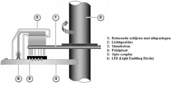
The steering angle sensor is mounted on the steering column. It can be located at the steering gear or inside the interior between the turn signal/wiper levers, as shown in the image on the right. These are the steering column switches of a BMW.
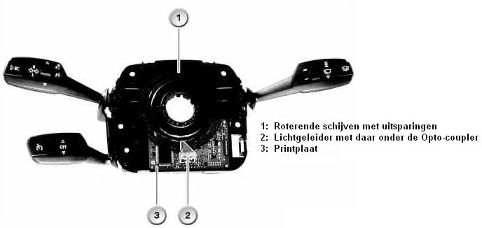
The steering angle sensor’s task is to measure the steering wheel’s rotation angle. This sensor uses one or more opto-couplers to measure the light passage through the rotating disks. At each point on a rotating disk, the light slits differ, allowing the exact position of the steering wheel to be identified. All the notches in the disks create an asymmetrical block signal. The opto-coupler can convert a light signal into a voltage, which is then transmitted to the control unit.
Lateral Acceleration Sensor (G-sensor):
The lateral acceleration sensor (also called the G-sensor due to the G-forces) is placed as centrally as possible in the car. During cornering, the movable plate (see the figure below, number 2) shifts between capacitors (1). The capacitors have a voltage of 5 volts. When the plate is centered (i.e., when the car is driving straight), the voltage on both capacitors is 2.5 volts. If the car takes a corner (in the case of the image to the left), the plate shifts as a result of centrifugal and centripetal forces.
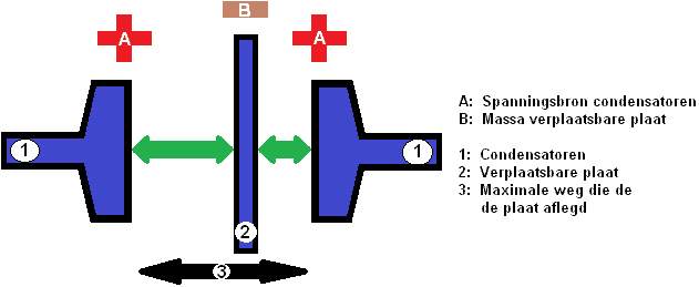
When the plate shifts, the capacity of the right capacitor decreases. It will now measure, for example, 1.5V instead of 2.5V. The ESP control unit recognizes the difference between the capacitors and can deduce how large the centrifugal or centripetal force is (i.e., how sharp the turn is taking place. This allows determination of whether the car is experiencing oversteer). Values from this lateral acceleration sensor are compared with data from the wheel speed sensors to determine if the ESP system should intervene.
Yaw Rate Sensor (Yaw sensor):
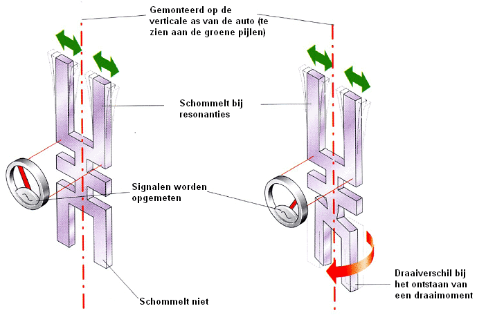
The yaw rate sensor, also known in English as the “Yaw sensor,” is placed as centrally as possible in the car, along with the lateral acceleration sensor. The sensor provides data needed by the ESP system. The yaw rate sensor detects the vehicle’s tendency to rotate about the vertical axis. The value of this measurement is called the turning rate and is expressed in degrees per second.
The sensor consists of two tuning forks. The upper tuning fork is excited to resonate at 11000 Hz (11 kHz) with an alternating voltage and rotates as the vehicle corners. The sharper the turn, the more the lower tuning fork twists relative to the upper fork. The principle relies on the gyroscopic forces (Coriolis force). When the rotating part is twisted from its position, gyroscopic forces arise. Hence the name yaw rate sensor.
Due to torsion, a piezoelectric element generates a voltage difference measured by the control unit. The generated voltage ranges between 0 and 5 volts. At rest (when no twist is recorded), the sensor outputs 2.5 volts.
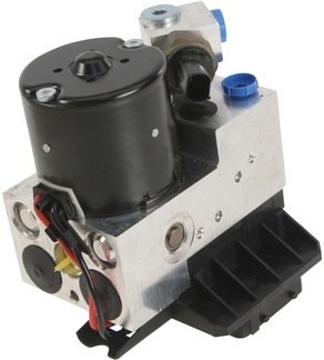
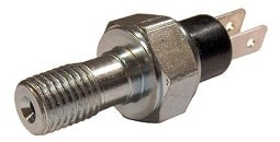
Brake Pressure Sensor:
Separate hydraulic pressure sensors are added to the brake system (in both circuits), as seen in the images below. In older cars, these sensors are located in the brake lines. Nowadays, the brake pressure sensors are usually integrated into the hydraulic unit of the ABS system itself. This unit is often visible under the hood. All hydraulic brake lines are connected here.