Drive Shaft:
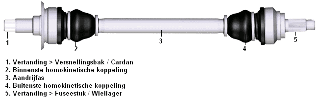
A drive shaft transfers the driving forces to the wheels. In front-wheel drive cars, the drive shaft is attached internally to the transmission and externally to the knuckle. In the image below, the shaft passes through the wheel bearing at number 5, which also features splines. The splines interlock, causing the wheel bearing to rotate with the flange when the drive shaft is powered.
In rear-wheel-drive cars, the transmission is usually longitudinally aligned with the engine and connected via the propeller shaft, distributing power to both drive shafts so the rear wheels are driven. Here too, the splines (figure number 5) are mounted in the wheel bearing.
Parts 1 and 5 in the image remain horizontal. Because the wheel needs to be able to spring up and down and make steering movements, there must be moving parts present in the drive shaft. These movements are made possible by using constant velocity joints. One end of the drive shaft is connected to the transmission or differential with a constant velocity joint, and the other end is attached with a constant velocity joint within the unsprung part of the suspension strut.�a0
The term “unsprung” means the section is below the spring and therefore follows the road (bumps/depressions). The sprung section of the car includes everything supported by the springs (and moves with the car’s compression and rebound). There is thus compression and elevation difference between the engine/transmission and the knuckle where the shaft sits. A completely straight shaft cannot be installed. The shaft will always need to create a certain angle at both sides. When the car is heavily compressed, the drive shaft (section 3) will be at a steeper angle than when the car is extended.
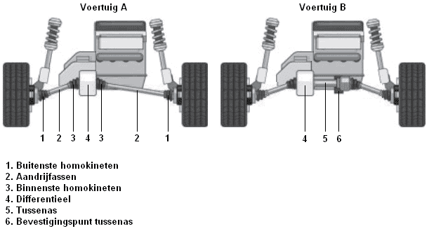
Since a long drive shaft can be detrimental to the construction of the vehicle, an intermediate shaft can also be installed. This is illustrated in the image.
In a chassis where a drive shaft from vehicle A does not fit—due to the subframe or control arm being in the way—one can choose to install an intermediate shaft. The intermediate shaft, as seen in vehicle B, is mounted horizontally in the differential. To the right of the intermediate shaft, the inner CV joint of the drive shaft is mounted. At this point, the drive shaft is fixed to a stationary point on the chassis or subframe.
This causes the drive shaft on the right to have a greater angle than in vehicle A.
Constant Velocity Joint:
A CV joint is also referred to as a Rzeppa joint (named after the inventor Alfred Hans Rzeppa). A CV joint allows the wheels to be driven while the vehicle can compress and steer. The joint is constructed such that the angle the drive shaft takes does not affect the rotational speed of the shaft. The speed of the inner CV joint is exactly the same as the outer. This is different than with a universal joint; an uneven motion occurs there.
The image below shows a CV joint applied to the wheel side. The drive shaft is visible at the bottom left. Additionally, the ball bearings and splines are shown, as the CV joint is placed at an angle here.

A protective boot covers the constant velocity joint, as shown in the upper image. Inside this boot is special molykote grease. The boot is very flexible but can occasionally tear, causing the grease to leak out. It is crucial to replace a torn CV boot/drive shaft boot as soon as possible, because the grease will disperse, allowing sand and other debris to enter. Sand and dirt will adhere to the grease, causing the CV joint to fail quickly. Once a CV joint is defective, a ticking sound will be heard on the wheel side when driving in a curve, and vibrations will occur on the transmission side during acceleration.
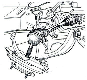
To replace the boot, the drive shaft must be dismantled. Sometimes the boot can be replaced while the drive shaft is still mounted on the final drive (the transmission or differential). The knuckle must be disconnected at the top or bottom. Often the outer tie rod end of the track rod needs to be removed from the knuckle. This can be seen in the image.
Once the drive shaft is removed from the knuckle, the clamp of the boot must be loosened first. The boot can be slid off the CV joint, after which the CV joint can be disassembled from the drive shaft. The CV joint can often be knocked off with a hammer; the snap ring is on the drive shaft, inside the CV joint. Occasionally, there is a snap ring on the drive shaft that must be removed before the CV joint can be slid off. Consult the manufacturer’s repair manuals for this.
When installing the CV joint, ensure the snap ring is seated correctly. If the snap ring is on the drive shaft and the CV joint needs to be slid over it, the CV joint must be pushed far enough onto the shaft. If not, the CV joint will slip off the shaft during steering movements. To check if the CV joint and snap ring are properly seated, check for play in both parts: there should be a slight amount of play. If the CV joint is completely fixed on the shaft, it may not be correctly seated.
Tripod Joint:
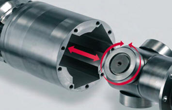
A tripod joint is often used on the inner side (transmission or differential side). This is not always the case; the CV joint described above is also frequently used. A tripod joint operates differently and can be identified by its larger housing. The image below shows the tripod joint.
The tripod joint typically features three rotating rollers that slide into slots in the housing. The rollers enable the drive shaft, like with the Rzeppa joint, to make a true rotating motion. The advantage of this joint is that the drive shaft can move back and forth over a long distance in the housing. This joint is prone to causing vibrations when worn. The splines in the housing will deform, forcing the rollers to move differently than intended, resulting in a vibration. This vibration can be felt in the steering wheel during acceleration, sometimes throughout the entire car. Removing the drive shaft easily reveals whether the tripod joint is worn out or if there is another cause. Once the grease is removed, irregularities in the housing can be felt by hand; if a dent or burr is detected, it is advisable to install a new joint.�0a0
Sometimes only one of the two tripod joints is defective. Given the high cost of these joints, it is worthwhile to check which joint is actually worn before replacing both sides preventively.
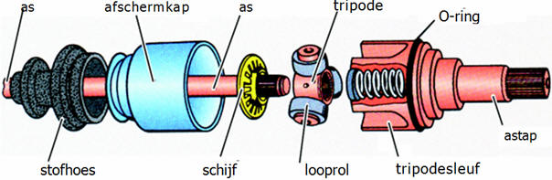
The image below shows an exploded view of a tripod joint.
Related page: