Topics:
Driver Assistance:
Systems categorized under “driver assistance” aid the driver in operating the vehicle. Generally, driver assistance aims to enhance safety. Often, multiple systems work together to achieve the desired effect. The following systems can be classified under driver assistance:
- LDW (Lane Departure Warning). Function: alert when crossing lane markings;
- TSR (Traffic Sign Recognition). Function: recognizing traffic signs and informing the driver;
- ACC (Adaptive Cruise Control). Function: automatically maintaining distance from the vehicle ahead;
- BSD (Blind Spot Detection). Function: alert for vehicles in the blind spot;
- ALC (Adaptive Light Control). Function: automatically switching lights on and off and sometimes swiveling the reflector;
- Precrash systems. Function: automatic braking to avoid collisions;
- Pedestrian detection. Function: pedestrian detection;
- Rain/light detection. Function: automatically activate wipers upon detecting rain;
- HDC (Hill Descent Control). Function: descending assistance;
- Hill hold/start assist. Function: control the parking brake when stationary on a hill and release when driving away;
- Surround view system. Function: 360-degree view system using various cameras;
- Adaptive high beam/curve lighting. Function: glare-free system for oncoming traffic;
- Automatic parking. Function: automatic parking system;
- Driver drowsiness detection. Function: detection of driver alertness, e.g., falling asleep.
- Navigation system. Function: navigating to the designated destination. In a hybrid car, the charge state can be adjusted based on the designated route.
A combination of the above systems forms a basis for an autonomous vehicle. Components such as radar, video cameras, and ultrasonic sensors expand the previously mentioned systems.
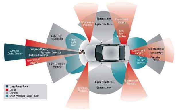
Radar:
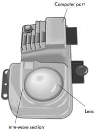
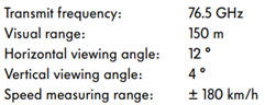
Radar has been used for several years to control automatic speed, braking, and safety systems in response to sudden changes in traffic conditions. The main function of the radar sensor is to detect objects and then determine their speed and position relative to the vehicle on which the sensors are mounted. To achieve this, the radar sensor has four antennas that simultaneously emit radar waves, usually at a frequency between 76 and 77 GHz. These waves are reflected by the object, which are then captured by the antennas. By comparing the phase differences and amplitudes of signal echoes, the positions of the objects can be determined.
The table below shows the different automotive applications for which radar is used.
Three types of radar systems are distinguished: Short- Mid- and Long-range radar.
- Short-Range Radar (SRR)
Reverse parking: when automatically parking, ultrasonic sensors are too slow to allow the computer to detect the distance between two cars, so SRR is also used here.
Pedestrian recognition: the system intervenes in unclear situations when a pedestrian approaches. If there is no timely response, the vehicle automatically brakes.
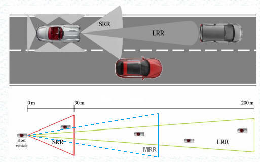
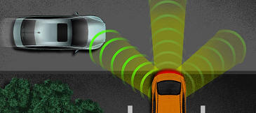
- Mid-Range Radar (MRR)
Cross Traffic Alert: when the driver reverses out of a parking space in a clear situation, the system warns of approaching vehicles (see image below).
- Long-Range Radar (LRR)
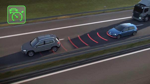
Active Cruise Control (ACC): with a range of 150 to 250 meters for vehicle speed detection from 30 to 250 km/h, the LRR is suitable as a radar system for active cruise control. The distance to the vehicle ahead can be set by the driver. Typically, 4 to 8 phases are possible. Each phase consists of several meters. The operation of active cruise control is explained below.
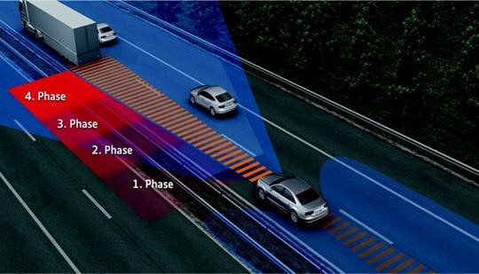
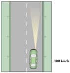
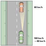
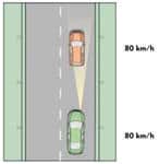
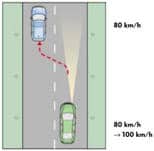
The Automatic Distance Control (ADC) can thus perform a braking intervention when an object is detected. The images below are of the ACC (Active Cruise Control) in a Volkswagen Phaeton.
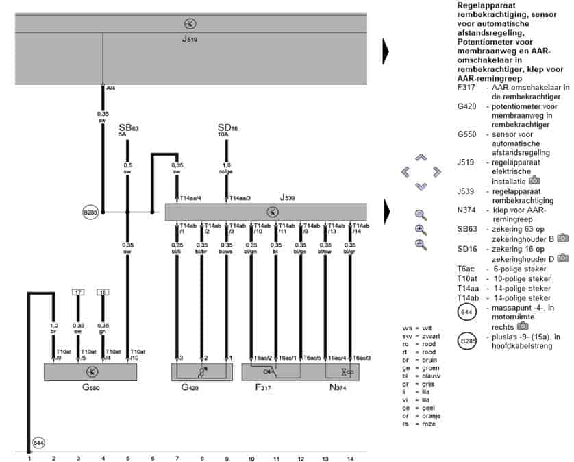
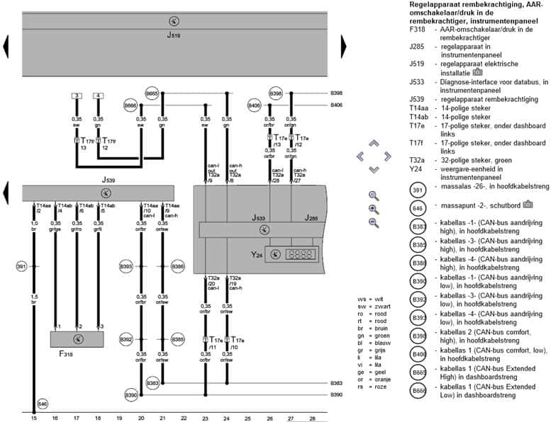
The electrical installation of the ACC is depicted in the following schematics. G550 is the sensor for automatic distance control. The wires from pin 4 and 5 refer to 17 and 18 in the following diagram.
References are made to positions 17 and 18 in the diagram below. These turn out to be CAN-bus wires (Extended Low) (B665 and B666) connected to control unit J533. Through CAN-bus drive high (B383 and B390), J533 communicates with J539 (control unit brake booster). In a subsequent diagram, more connections to this control unit are shown.
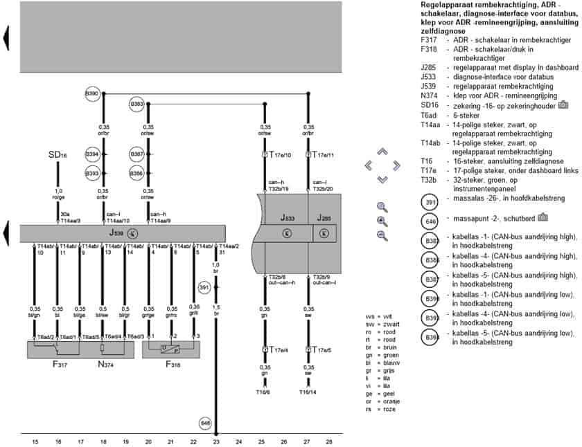
Control unit J539 controls the N374 valve for ADR (Automatic Distance Regulation) and the F318 (servo on the brake booster) for a braking intervention. Here again, the CAN-high (B383) and CAN-low (B390) wires from the previous diagram can be seen.
Lidar:
LIDAR (Light Detection And Ranging or Laser Imaging Detection And Ranging) is a technology that determines the distance to an object or surface using laser pulses. Lidar works similarly to radar: a signal is transmitted and will later be received by reflection. The distance to this object is determined by measuring this time. The difference between lidar and radar is that lidar uses laser light, while radar uses radio waves. As a result, lidar can detect much smaller objects than radar. The wavelength of radio waves is around 1 cm, while that of laser light is between 10 μm (ir) and 250 nm (uv). At this wavelength, the waves will be better reflected by small objects.
A lidar sensor emits a modulated, continuous infrared signal, which is reflected by an object and then received by one or more photodiodes in the sensor. The modulated signal can consist of square waves, sine waves, or pulses. The modulator sends the received signal to the receiver. The received signal is compared with the transmitted signal to check for a phase difference and to verify the time between transmission and reception. The distance to the object is determined from this data.
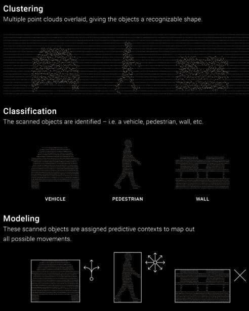
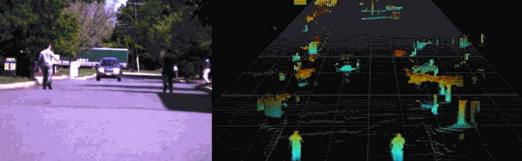
Lidar systems operate at the speed of light, which is more than 1,000,000 times faster than the speed of sound. Instead of emitting sound waves, they send and receive hundreds of thousands of laser pulses per second, with an onboard computer recording the reflection point of each laser and translating this rapidly updating “point cloud” into an animated 3D representation of its environment.
Not only is the object shown on a screen, but the computer also estimates the possible movements of the object. A vehicle can quickly move forward and backward but not sideways. However, a person can move in any direction but at a relatively slow speed. The lidar system takes a snapshot of the situation the car is in, with the driver assistance making over a hundred choices every minute to drive safely.
The composition of a lidar sensor is as follows:
- Light source: this can be a laser, LED, or VCSEL diode that emits light in pulses;
- Scanner and optics: these components guide the light through a mirror or lens to the outside. The lens focuses the reflected light onto a photodetector;
- Photodetector and electronics; the light is captured in a photodetector, for example, a photodiode. The electronics process the image data digitally;
- Position and navigation system: mobile lidar systems require a GPS system to determine the exact position and orientation of the sensor.
Autonomous driving with Lidar:
- Google combines lidar and radar;
- Intel relies entirely on camera technology;
- Agreement among manufacturers: they combine visual (camera) images with sensor information.
- If one system fails, the other technology will still detect and intervene to achieve a safe mode.