Introduction:
A diode is added to many electronic circuits, for example, as a rectifier in an alternator or radio, or as a freewheeling diode in a coil. This page discusses the operation and various functions of the diode.
Diode as polarity protector and rectifier:
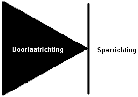
The diode in a system provides rectification. The current can only flow in one direction and is blocked in the opposite direction. This is illustrated in the image below. This is often done to protect components from incorrect connections (as a so-called polarity protector, when + and – are reversed). If the power and ground are reversed on a component, the diodes internally ensure that the voltage is blocked to prevent damage to, for example, the circuit board.
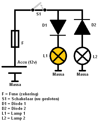
In the following image below, the basic function is shown. a0Diode D1 is conducting, D2 is in the blocking direction. It is easy to remember that the current flows in the direction where the arrow points. At D1, the current is allowed through and reaches lamp L1. The lamp will now light up. Lamp L2 will not because this diode is in the blocking direction. Instead of a lamp as in this example, there can be all sorts of components that could be irreparably damaged if connected incorrectly.
Diodes are also used in alternators to rectify current. An alternator generates alternating current, which needs to be converted to direct current. This is made possible by using multiple diodes (on the diode bridge). a0For more information about diodes as a rectifier in an alternator, see the rectifying diodes chapter on the alternator page.
Freewheeling diode:
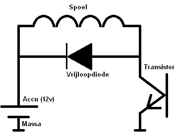
A high voltage is generated in a coil, such as in an ignition coil. The voltage passing through the coil is switched on and off by the transistor. However, when the transistor stops conducting (the supplied current to the base is turned off), the coil is still full of residual energy. The coil cannot be directly ’empty’ after the transistor is turned off. An inductive voltage is always released after switching off, which can be many times higher than the vehicle’s voltage of 14 volts.
The consequence is that this inductive voltage keeps the transistor switched on. The coil, through this inductive effect, keeps the transistor conducting even if it is switched off (on the base of the transistor).
To prevent this, a freewheeling diode is added to the system. When the transistor turns off, the inductive voltage flows through the freewheeling diode to the positive connection of the coil. Since the inductive voltage no longer reaches the transistor, it remains off.
Technical operation of a diode:
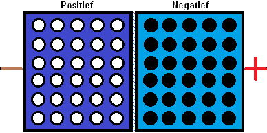
A diode consists of a piece of Positive silicon and a piece of Negative silicon. The plates contain holes, with positive ions and negative electrons. These move as the current direction changes.
These P and N silicon plates are placed against each other. The current flows from positive to negative (forward direction). If the current wants to flow from negative to positive (reverse direction), it is blocked. In the images below, it is shown how this happens:
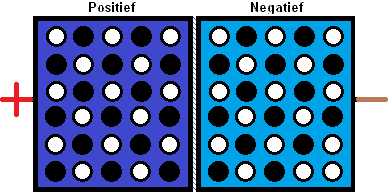
Reverse direction:
In the image below, the diode is blocked. The – is now, for example, connected to a voltage source and the + to ground. The diode ensures no current flows from – to +.
The negative electrons have all moved to the plate with the Negative silicon. The plate with the Positive silicon, thus with the positive ions, does not conduct. The “holes” are empty, so no conduction and therefore no current transfer can occur.
Forward direction:
The current flows from + to -, thus in the image from left to right. The positive electrons and negative electrons are mixed. The holes at P are now filled by the negative electrons, creating a conductive effect (the forward direction). a0There is a voltage loss because there is resistance (the passage is not entirely pure). This voltage is called the diffusion voltage, and it is always approximately 0.7 volts.
Related pages: