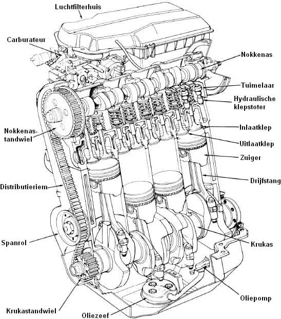
Introduction:
The spaces in which the pistons move up and down are called cylinders. The inside of the cylinder is not completely smooth, because then the oil could easily move past the piston from the crankcase to the combustion chamber. That is why honing grooves are applied. The principle of honing is described later on this page.
The size of the cylinders determines the engine displacement. For each type of engine, a displacement is used of e.g. 1.6, 2.0 or sometimes as much as 6.0 litres. That means (for a 1.6) that, when all cylinder spaces are added together, there is room for 1.6 litres of air. The space is measured between the piston at BDC (so at the bottom and starting the compression or exhaust stroke) up to the cylinder head. The larger the displacement, the higher / wider the cylinders are. This also depends on the bore (the diameter of the cylinder) and the stroke (the height of the cylinder).
The displacement can be calculated with the data bore x swept volume. More information about displacement and bore x swept volume can be found on the page Calculating engine displacement.
More information about the 4-stroke process can be found on the pages Petrol engine and Diesel engine.
Types of cylinder liners:
The cylinders can be bored directly into the engine block, cast as one complete engine block, or they can consist of separate inserted liners. Bored cylinders, or cylinders cast as one piece, are called dry cylinder liners and the separate cylinder liners are also called wet cylinder liners. Wet liners can be replaced separately and can be placed by hand. They come into direct contact with the coolant and have a thicker wall than dry liners. After all, they must be sufficiently sturdy on their own. To prevent fluid from entering the oil sump along the wet cylinder liners, extra gaskets are used.
In air-cooled engines, the cylinders form a separate assembly; these are fitted with cooling fins and are mounted on the crankcase. The surface area of the fins depends on the degree of cooling required.
When a cylinder head is removed from an engine block with separate cylinder liners, great care must be taken to ensure that the liners have not shifted upwards. Otherwise, problems may arise when refitting the cylinder head.
To check this, a kind of large straightedge or a perfectly straight piece of iron must be placed across the full width of the engine block. If a cylinder liner protrudes, this will be noticed immediately. The cylinder liner can then be tapped down with light force (carefully!).
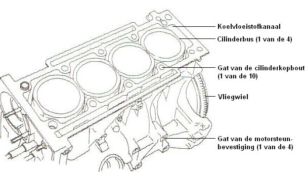
The image on the right shows an engine with wet cylinder liners and the image below an engine block with cast or bored cylinders.
Between the engine block and the cylinder head, the head gasket is fitted. The head gasket provides the seal between the cylinders and between the oil and coolant channels.
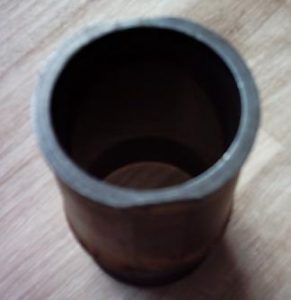
Honing:
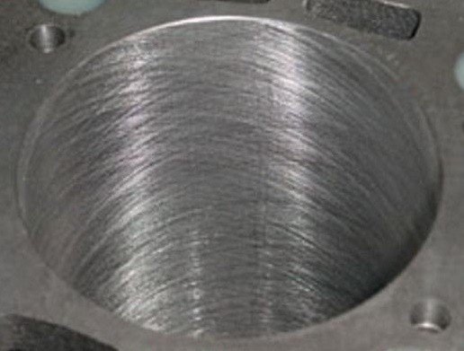
A cylinder wall is not nicely smooth on the inside. If it were smooth and the piston moved up and down in it, there would always be a quantity of lubricating oil getting past the piston along the cylinder wall into the combustion chamber above the piston. And that is precisely not the intention. Also, when the engine has been standing still for a while, there would no longer be any engine oil between the piston and the cylinder wall. The engine would then run “dry” for a moment before engine oil creeps back up past the piston. To prevent that, small honing grooves are applied in the cylinder wall. (Also on the side of the piston, but that will be discussed later). Honing grooves are nothing more than small scratches applied in the cylinder wall at a certain angle, in which the oil partly remains.
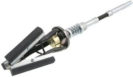
The honing grooves are usually applied at an angle of 47 degrees, or sometimes 90 degrees to each other, using a special honing tool that is mounted on a drill. Special honing tools are shown in the images below.
Honing the cylinder must be done very carefully. Too few honing grooves results in higher oil consumption, and too many causes damage to the protective layer in the cylinder wall.
During engine overhaul, the cylinder is sometimes bored out and an oversize piston is fitted. The total displacement then becomes larger, so it must be honed again. Engines that suffer greatly from oil consumption—where the grooves have become smooth—or engines that have a light scratch in the cylinder wall can also be restored again with a honing tool. If there is a deep scratch in the cylinder wall, e.g. from an object that has entered the combustion chamber, the scratch may be so deep that honing is no longer worthwhile. Then only boring the cylinder wall and fitting an oversize piston still makes sense, or otherwise a new engine must be fitted.
Light grooves must also be applied to the side of the piston. These also have the task of retaining a little oil for lubrication. When the pistons are smooth and the honing structure has disappeared, oil consumption can increase. The best measure for this is to replace the pistons and check the honing grooves in the cylinder wall.
The honing grooves can wear (faster) when driving conditions are not optimal, such as:
- Driving too hard with a cold engine: the piston is pressed hard against the cylinder wall by the lateral force, while the engine has not yet reached temperature and the piston has not yet expanded properly due to the temperature. More information about piston expansion can be found on the page piston.
- Lack of lubrication, or driving far too long with old (thick) oil and therefore also a lubrication shortage.
Cylinder configurations:
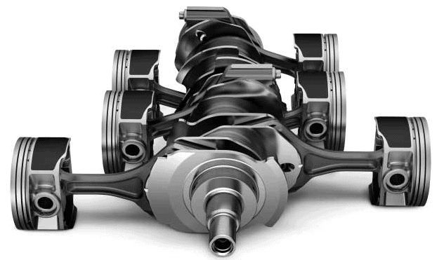
There are two-, three-, four-, five-, six-, eight-, ten- and twelve-cylinder engines. Bugatti even has the sixteen-cylinder in the Veyron. The cylinders can be arranged vertically one behind the other. This is then called an inline engine.
The cylinders can also be arranged in a V-shape at 60 or 90 degrees: this is called a V-engine (for example a V6 or V8). If the cylinders are placed horizontally to the left and right of the crankshaft, it is a boxer engine.
The more cylinders an engine has, the more smoothly it runs and the more even the delivered torque is. After all, there are more power strokes distributed over two rotational frequencies, or 720 degrees of the crankshaft. The flywheel can also be made lighter with a higher number of cylinders. Balance shafts, which are necessary in 2- and 3-cylinder engines to damp engine vibrations originating from the vibrations of the power strokes, are not needed on an 8-cylinder engine.
- Inline engine: The cylinders are arranged vertically one behind the other. This configuration is the most common. Modern inline engines usually have 4 cylinders, but nowadays the economical, environmentally friendly 3-cylinders are also found in e.g. the VW Polo, and the 2-cylinders at Fiat. BMW always uses an inline 6, never a V-shape.
- V-engine: The cylinders are arranged at an angle of 60 or 90 degrees. The most common engines here are the V6 and V8 engines.
There are also V5, V10 and V12 engines. In the V12 engine, there are 6 cylinders on one side of the V-shape, and the other 6 on the other side. - VR engine: A combination of an inline and a V-engine. This is mainly used by Volkswagen, which is known for the VR5 and VR6 engines. In a Golf R32, the cylinders are at an angle of 15 degrees to each other. This combines the advantages of the inline and V-engines. With an inline engine, the advantage is that the engine can be equipped with 1 cylinder head, and with a V-engine the forces from the piston / connecting rod can be transmitted to the crankshaft at a larger angle relative to each other.
- W-engine: The cylinders are arranged in a W-shape. This was used in the W12 engines of the VW Touareg, the Phaeton, Audi and the Q7.
You can basically see this engine layout as two V-engines mounted to one crankshaft. The advantage of a W-engine is that, given the number of cylinders, the length of the block is reduced compared to the V-engine. There will be slightly more space between the radiator and the bulkhead. It does mean that the space at the sides of the engine block between the cross members is reduced.
Repair work and maintenance (such as replacing the spark plugs) do not become any easier. To remove the cylinder heads, it will be necessary to remove the complete engine from the car.

- Boxer engine: The cylinders are arranged horizontally at an angle of 180 degrees.
The cylinders are arranged horizontally opposite each other at an angle of 180 degrees. The advantages of this flat engine are that the car’s centre of gravity is immediately much lower. The engine will also suffer less from vibrations, because the piston vibrations cancel each other out. The engine is therefore much better balanced and therefore does not need separate balance shafts. Boxer engines are used in both passenger cars and motorcycles. Subaru is known for using boxer engines, as are the Citroën 2CV and the old VW Beetle.
Firing order:
The firing order is the sequence in which the mixture is ignited in the cylinders one after another. The firing order depends on the engine design and the way the load is distributed over the crankshaft. The table shows the common firing orders.
| Engine type: | Number of cylinders: | Firing order: |
| Inline engine: | 3 | 1-3-2 |
| 4 | 1-3-4-2 or 1-2-4-3 | |
| 5 | 1-2-4-5-3 | |
| 6 | 1-5-3-6-2-4 or 1-5-4-6-2-3 or 1-2-4-6-5-3 or 1-4-2-6-3-5 or 1-4-5-6-3-2 | |
| 8 | 1-6-2-5-8-3-7-4 or 1-3-6-8-4-2-7-5 or 1-4-7-3-8-5-2-6 or 1-3-2-5-8-6-7-4 | |
| V-engine: | 4 | 1-3-2-4 |
| 6 | 1-2-5-6-4-3 or 1-4-5-6-2-3 | |
| 8 | 1-6-3-5-4-7-2-8 or 1-6-2-8-3-7-4-5 or 1-3-7-2-6-5-4-8 or 1-5-4-8-6-3-7-2 or 1-8-3-6-4-5-2-7 | |
| 10 | 1-6-5-10-2-7-3-8-4-9 | |
| 12 | 1-7-5-11-3-9-6-12-2-8-4-10 or 1-12-5-8-3-10-6-7-2-11-4-9 | |
| Boxer engine: | 4 | 1-4-3-2 |
| 6 | 1-6-2-4-3-5 |