Topics:
Control Units:
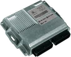
Modern cars are equipped with many different control units, each with its own function; the engine control unit receives information from all the sensors in the engine compartment and controls the actuators. The image on the right shows an engine control unit, also known as an Electronic Control Unit (ECU).
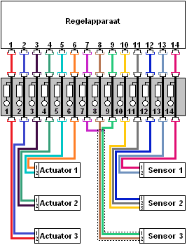
This engine control unit is connected to two plugs with often more than 100 individual wires. Each wire has its own function; for example, pin number 6 receives information from the coolant temperature sensor, and via pin 81, the ECU controls the fuel injector of cylinder 1. All sensors in the engine compartment send their information to the ECU. This information is processed by the engine management system within the ECU into what is known as a map. An example is shown in the image below:
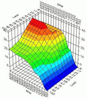
In the map, data from sensors are used, such as the ambient temperature, coolant temperature, throttle position, turbo pressure, values from the lambda sensors, engine speed, etc. Based on this data, the ECU determines when the injector should open and how long it stays open (the longer it’s open, the more fuel is injected), as well as the ignition timing, turbo control, etc.
Because the injection amount, ignition, and turbo pressure depend on engine speed and load, it is important for the ECU to process this data accurately.
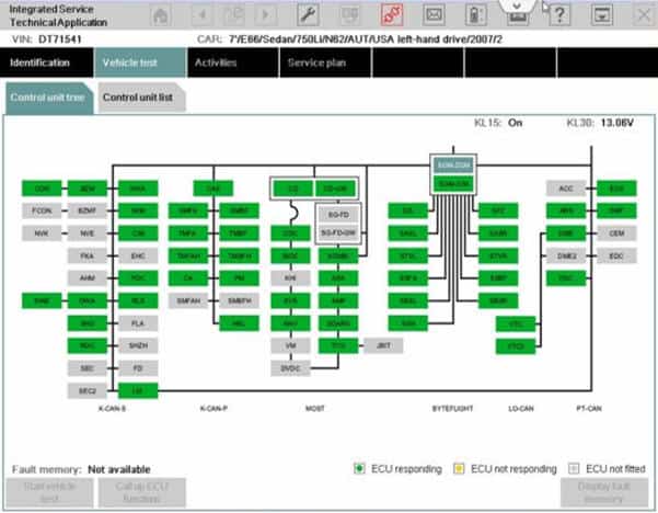
Modern cars often contain dozens of separate control units. The image shows a screenshot from a BMW diagnostic computer.
This screen is from a 2007 BMW 7 Series. Each green and gray block represents one control unit, totaling 76 control units. Black lines represent the cables connecting the control units, including CAN-bus cables. BMW assigns its own names to different networks (K-CAN-S, K-CAN-P, BYTE-FLIGHT, LO-CAN, PT-CAN). Each network has its own speed and is connected via a Gateway.
In the comfort network, all control units related to the vehicle’s interior and body are connected via CAN-bus wires. This is called the CAN-B (comfort bus). The image below shows which control units fall under the term “comfort.”
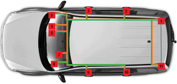
1. Trailer Hitch Control Unit
2. Right Rear Door Control Unit
3. Right Front Door Control Unit
4. Gateway
5. Comfort Control Unit
6. Alarm System Control Unit
7. Instrument Cluster
8. Steering Column Electronics Control Unit
9. Left Front Door Control Unit
10. Left Rear Door Control Unit
11. Park Distance Control Unit
The various control units can be mounted throughout the car; in the dashboard, doors, trunk, above the headliner, you name it. Technicians can look up the location of the relevant control unit in the workshop documentation or even in the diagnostic equipment. This example shows only a small number of control units. In reality, there can be dozens.
Apart from the comfort bus (CAN-B) in the example, there is also a drivetrain bus (CAN-C). The drivetrain bus handles all communication from the engine to the wheels. A key difference between these two buses is speed: CAN-B operates at a maximum speed of 125kbit per second, while CAN-C operates up to 1Mbit per second. The speed for controlling the power seat adjustment (CAN-B) does not need to be as high as the communication between safety systems of the Anti-lock Braking System (ABS).
In addition to the various CAN-bus systems with different speeds, there are other network systems to enable communication among control units, such as LIN-bus and MOST-bus. To connect these networks, a Gateway is used. Without this gateway, control units from the CAN-A network cannot communicate with the CAN-B network. The gateway essentially acts as a hub and a translator between the different networks. Click here for more information about the Gateway and different types of networks.
When voltages or signals need to be measured at the control unit’s connector, a breakout box can be placed between the wiring harness and the control unit (see image below). The breakout box contains numerous test points. Click here to go to the page about the breakout box.